Stamping die with braking function

A stamping die and function technology, applied in forming tools, manufacturing tools, safety equipment, etc., can solve the problems of continuous punching, defective accessory tools, insufficient sensitivity and reliability of clutches and brakes, etc., and achieve the effect of protection and safety.

Inactive Publication Date: 2013-09-18
SUZHOU HAIERSHI INFORMATION TECH CO LTD
View PDF7 Cites 4 Cited by
  • Summary
  • Abstract
  • Description
  • Claims
  • Application Information

AI Technical Summary

Problems solved by technology

For example, the punch itself has defects, the lack of safety protection devices, the clutches and brakes are not sensitive and reliable enough, the electrical control structure suddenly loses control and continuous punching occurs, and the accessories are defective, etc., all of which are important causes of accidents.

Method used


Image

  • Stamping die with braking function
  • Stamping die with braking function

Examples


Embodiment

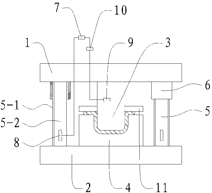
[0015] The stamping die with braking function of the present embodiment, such as figure 1 and figure 2 As shown, it includes an upper mold base 1 and a lower mold base 2 arranged oppositely, the upper mold base 1 is provided with a punch 3 , and the lower mold base 2 is provided with a die 4 .

[0016] The die 4 is formed with a die groove cooperating with the punch, and the die 4 is provided with a pressing plate 11 for pressing the edge of the stamped part.

[0017] The lower mold base 2 is fixed with an I-shaped vertical guide column 5, and the upper mold base 1 is provided with a square guide sleeve 6 that is slidably matched with the vertical guide column 5.

[0018] The side surfaces of the wing plate 5 - 1 of the upright guide post 5 are slidably fitted with a pair of inner side surfaces opposite to the square guide sleeve 6 .

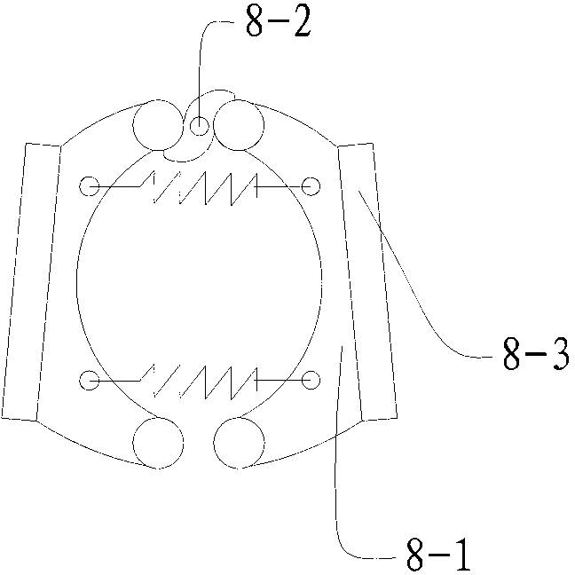
[0019] A brake 8 connected to an external brake pipeline 7 is provided on the web 5-2 at the lower end of the vertical guide column 5 . The...


PUM


Abstract

The invention relates to a stamping die with a braking function and belongs to the technical field of metal stamping. The stamping die comprises an upper die seat, a lower die seat, a male die, a female die, a vertical guide post and a square guide sleeve, wherein a female die groove is formed in the female die; a press plate is arranged on the female die; the side surfaces of a wing plate of the vertical guide post are in sliding fit with a pair of opposite inner side surfaces of the square guide sleeve; a brake connected with an external brake pipeline is arranged at the lower end of the vertical guide post and comprises a pair of brake shoes arranged oppositely, one ends of the brake shoes are hinged to a web plate of the vertical guide post, and the other ends of the brake shoes are in rolling connection with a driving cam; an inclined plane inclined to the other end of the brake shoe and friction plates arranged on the inclined plane are formed on each brake shoe; when the square guide sleeve is positioned at the brake at the lower end of the vertical guide post, the driving cam drives the brake shoes to rotate and enable the friction plates to be clung to and locked with the other pair of opposite inner side surfaces of the square guide sleeve. The stamping die has the advantage that in case of a danger, a mini-type punch can be emergently braked to protect personnel security.

Description

technical field [0001] The invention relates to a die, which belongs to the technical field of metal stamping. Background technique [0002] Stamping processing in mechanical processing occupies an important position in the processing industry of the national economy. The application fields of sheet metal parts are extremely wide, and they penetrate into all aspects of the manufacturing industry. Sheet metal forming is mainly realized by stamping dies. Using the stamping process, it has a series of advantages such as high precision, high efficiency, good quality, cost saving, material and energy saving. [0003] At present, many enterprises still use the simple manual operation method when using the stamping method to process and produce, that is, to directly load and take parts in the mold cavity by hand, and a large number of stamping equipment are responsible for the manufacture of various products or various processes. Task. In this case, if the stamping equipment and...

Claims


Application Information

Patent Timeline
Patent Type & Authority Applications(China)
IPC IPC(8): B21D37/12B21D55/00
CPCB21C51/00B21D37/10B21D37/12B21D55/00
Inventor 唐全林张智明徐金明
Owner SUZHOU HAIERSHI INFORMATION TECH CO LTD
Why Eureka
Try Eureka