Eureka AIR delivers breakthrough ideas for toughest innovation challenges, trusted by R&D personnel around the world.

Automatic feeding device of punching machine

A technology of automatic feeding and punching machine tools, applied in the directions of feeding devices, positioning devices, storage devices, etc., can solve the problems of easy disability, high cost, stagnant work efficiency, etc., to improve work efficiency, work safety and reliability. , the effect of ingenious design structure

Inactive Publication Date: 2013-09-18
舟山神鹰车辆配件制造厂
View PDF5 Cites 5 Cited by
  • Summary
  • Abstract
  • Description
  • Claims
  • Application Information

AI Technical Summary

Problems solved by technology

If the operator does not move quickly, it is easy to cause disability; furthermore, due to the limitation of human physical ability, the work efficiency is stagnant and cannot be improved.
[0003] At present, the feeding devices used on stamping machine tools mainly include robots or manipulators, but these devices use a large number of sensors or motion control devices, and the control of the feeding process is too complicated, resulting in high costs and difficult large-scale application or promotion.
Chinese invention patent 201010148918.2 discloses a feeding device, including moving devices such as transmission shafts and meshing gears. The structure is complex, the cost is high, and there are also problems with installation and matching accuracy.

Method used


Image

  • Automatic feeding device of punching machine
  • Automatic feeding device of punching machine
  • Automatic feeding device of punching machine

Examples


Embodiment Construction

[0014] The present invention will be further described in detail below in conjunction with the accompanying drawings and embodiments.

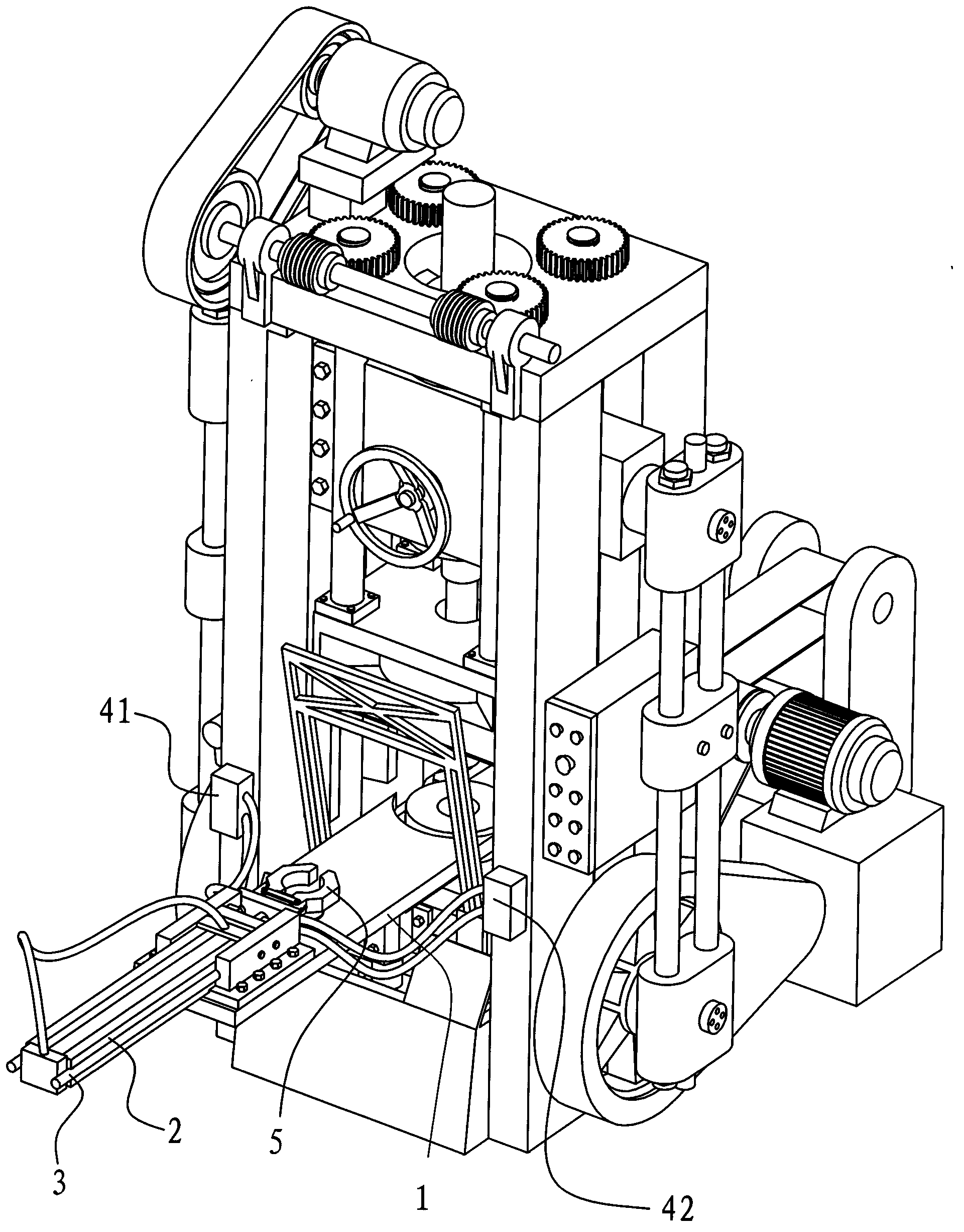
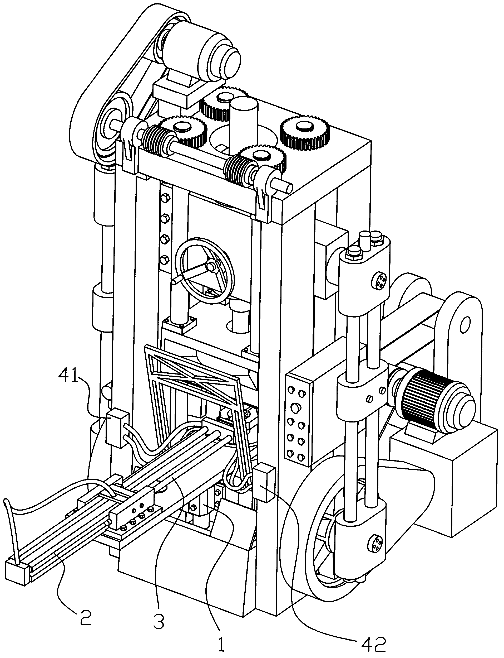
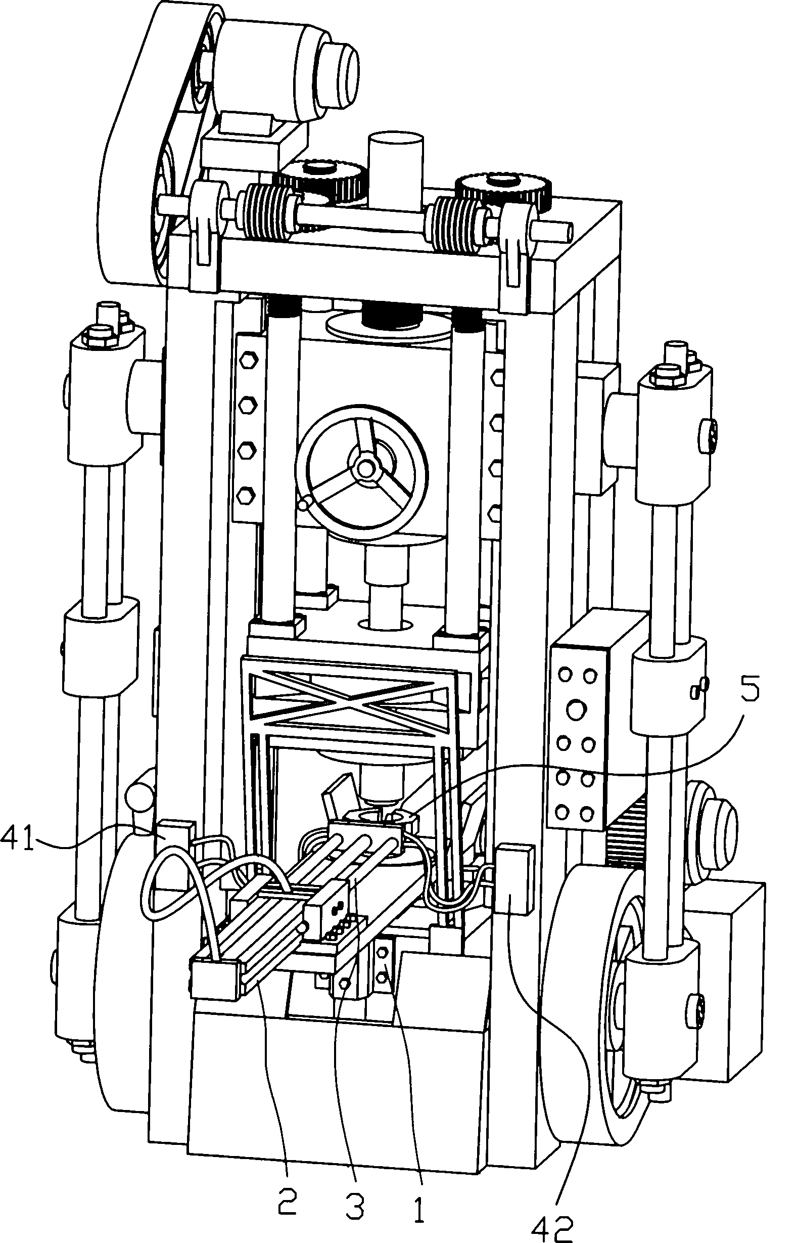
[0015] Such as Figure 1 to Figure 4 As shown, the automatic feeding device of the stamping machine tool in this embodiment includes a frame 1 horizontally installed on the side of the stamping machine tool work platform, the table on the frame 1 is on the same working plane as the stamping machine tool work platform, and the frame is provided with Slide rail 2, slide rail 2 are provided with the push rod 3 that cooperates with slide rail 2, and the front end of push rod 3 is provided with manipulator 5, also comprises the driver 41 that connects and controls push rod 3, and connects and controls manipulator 5 The driver 42; the slide rail 2, the push rod 3, the drivers 41, 42 and the manipulator 5 together form a push module, the driver 41 controls and drives the push rod 3 to reciprocate on the slide rail 2; the driver 42 controls and drives...


PUM


Abstract

The invention discloses an automatic feeding device of a punching machine, which is characterized by comprising a rack (1) horizontally mounted on the side surface of a working platform of the punching machine, a driver (41) and a driver (42), wherein a slide rail (2) is arranged on the rack (1); a push rod (3) matched with the slide rail (2) is arranged on the slide rail (2); a manipulator (5) is arranged at the front end of the push rod (3); the driver (41) is connected with and controls the push rod (3); the driver (42) is connected with and controls the manipulator (5); the slide rail (2), the push rod (3), the driver (41), the driver (42) and the manipulator (5) form a push module; the driver (41) controls and drives the push rod (3) to make reciprocating motion on the slide rail (2); the driver (42) controls and drives the manipulator (5) to release or firmly grasp a workpiece; and the driver (41) and the driver (42) control the push rod (3) and the manipulator (5) to act synchronously with the punching machine respectively. The automatic feeding device can work with the punching machine synchronously, is good in coordination, can be matched with various punching machines for use, works safely and reliably, and can improve the working efficiency of the machine.

Description

technical field [0001] The invention relates to the field of stamping processing equipment, in particular to an automatic feeding device for a stamping machine tool. Background technique [0002] The design principle of stamping machine (also known as punching machine) is to drive the slider through the crankshaft and connecting rod, so that the slider can make a linear reciprocating motion, and then punch the workpiece. Generally, the slider die part of the stamping machine tool is provided with an upper die, and the working platform of the stamping machine tool is provided with a lower die, and the processing of the workpiece is completed through the cooperation of the upper die and the lower die. With the continuous development of the mechanical processing industry and the increasingly fierce market competition, the requirements for the use of stamping machine tools are getting higher and higher, and the existing stamping machine tools still generally have manual feeding ...

Claims


Application Information

Patent Timeline
IPC IPC(8): B21D43/10B21D43/13
Inventor 任贤安任宏斌
Owner 舟山神鹰车辆配件制造厂
Why Eureka
Eureka Blog
Learn More