
Taro cutting machine

A taro and slicer technology, which is applied in metal processing and other directions, can solve problems such as inability to cut taro, unsuitable taro, and complex structure, and achieve the effects of improving slice quality, avoiding hand injuries, and high processing efficiency

Inactive Publication Date: 2013-09-18
福建省新润食品有限公司
View PDF1 Cites 16 Cited by
  • Summary
  • Abstract
  • Description
  • Claims
  • Application Information

AI Technical Summary

Problems solved by technology

And it is round. After peeling and washing, the surface is very slippery and easy to roll on the chopping board. Therefore, if you do not operate carefully when slicing by hand, it is very easy to hurt your hands.
[0003] There are also some slicers used for food slicing on the market, for example, the application number 200980104597.1 discloses "device and method for slicing vegetables", which can slice potatoes, but the structure is complicated; application number 201110196867 discloses The "Rotary Disc Potato Slicer" is used for slicing potatoes. However, since taro is much harder than potatoes, this device relies on the method of turning the dial by hand. It may not be able to cut taro, and it is not suitable for taro.

Method used


Image

  • Taro cutting machine
  • Taro cutting machine
  • Taro cutting machine

Examples


Embodiment 1

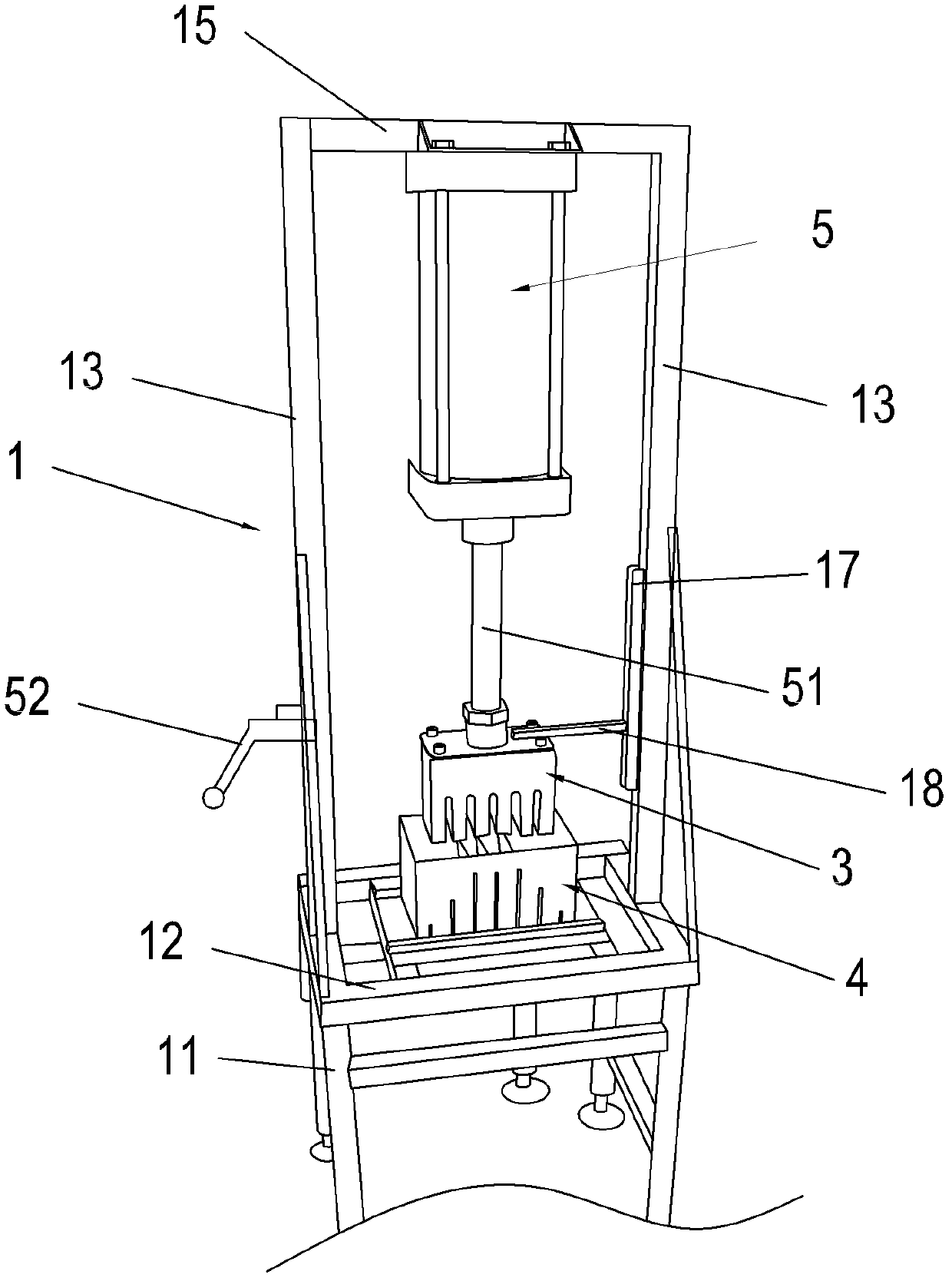
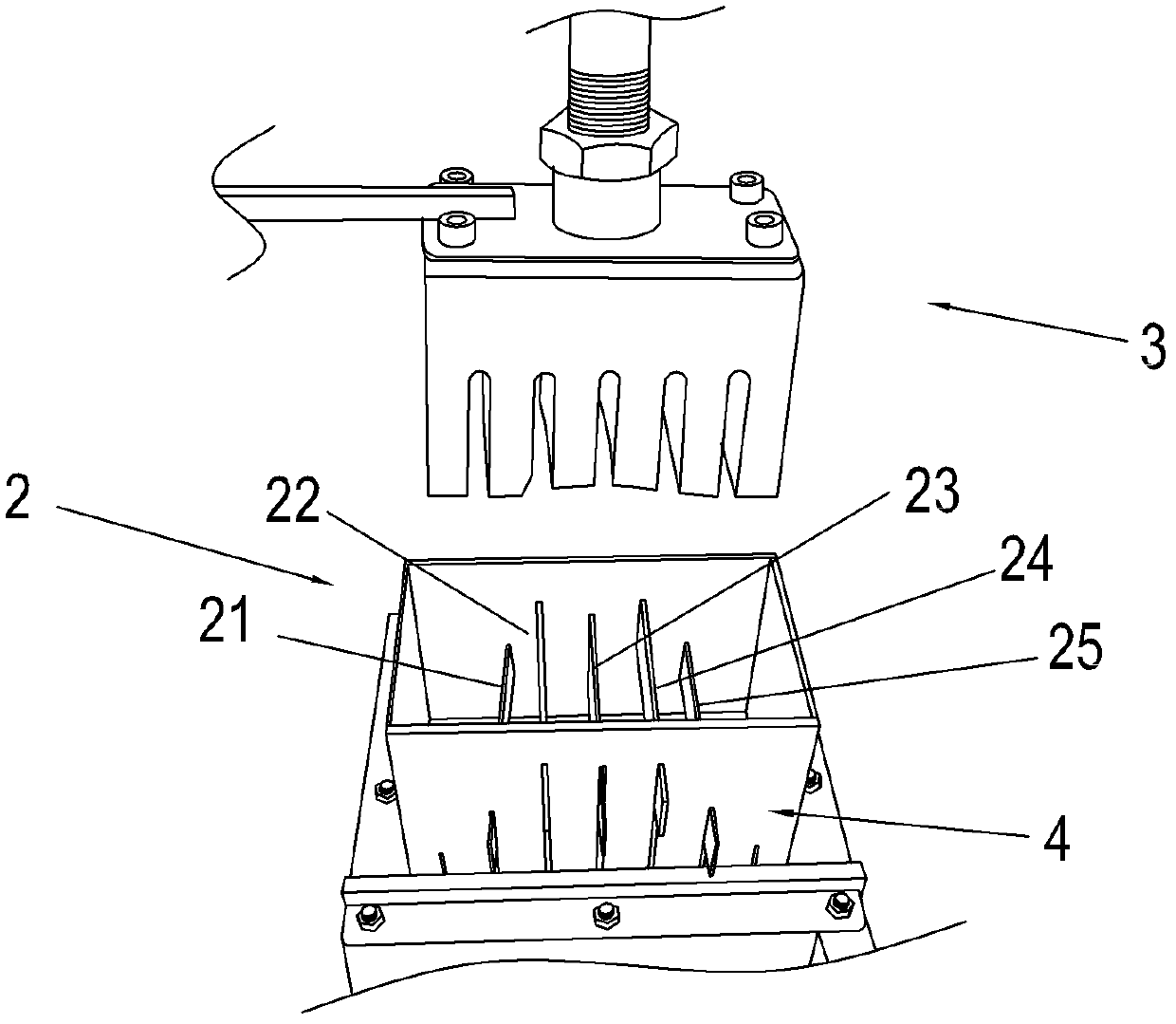
[0031] For specific embodiments of the present invention, refer to Figure 1 to Figure 3 , a taro cutting machine mainly consists of a bracket 1 and a slicer, wherein the slicer includes a knife set 2 and a pressing block 3, and the knife set 2 is arranged in a square frame 4.

[0032] This support 1 comprises a platform 12, and its center is provided with slicing device 2; Rod 15 is connected, and a cylinder 5 is fixed under cross bar 15, and the end of the push rod 51 of cylinder 5 fixes briquetting block 3, and the position of this briquetting block 3 and the position of square frame 4 match correspondingly. The support rod 13 on the left is also provided with an operation switch 52 for controlling the operation of the cylinder 5 .

[0033] In this embodiment, the cutter set includes five cutters 21 , 22 , 23 , 24 and 25 . The square frame 4 is open up and down, and on the opposite front and rear side walls, five tool jacks are set horizontally, namely the jacks 41, 42, 4...

Embodiment 2

[0038] The implementation of this embodiment is basically the same as that of Embodiment 1, the difference is that in this embodiment, the positions of the knives are different, specifically: the upper row is the knives 21, 25, and the lower row is the knives 22, 24 , the middle is cutter 23. For the corresponding socket arrangement, see Figure 5 . And there is a stagger between the upper and lower rows of tool sockets (see the dotted line in the figure), the cutter is in the shape of a rectangular parallelepiped, there are no protrusions at both ends, and the width is the same as the socket, so that the tools are also staggered by about 0.5cm after insertion .

Embodiment 3

[0040] see Figure 6, the implementation of this embodiment is basically the same as that of Embodiment 1, the difference is that in this embodiment, the square frame 4 is provided with upper, middle and lower rows of tool insertion holes on the vertical plane, and each row has A plurality of sockets 41, when in use, the cutter can be inserted in different sockets as required. That is, in this implementation, the number of tool insertion holes is greater than the number of tools. Can be on the same vertical line (or mutually staggered) between the upper and lower rows of jacks. The thickness of the slice can be adjusted by inserting the knife in different positions. In addition, the jacks 41 can also be arranged in more rows on the vertical plane, such as 4 rows or 5 rows, whereby each taro can be cut into more slices. The shape of the square frame can also be changed to other shapes, as long as the inside can accommodate taro to pass through.


PUM


Abstract

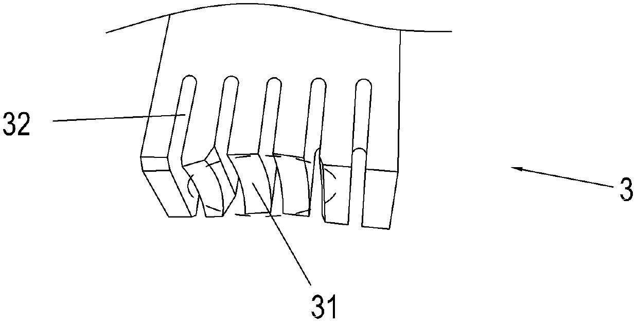
The invention discloses a taro cutting machine, which comprises a support and at least one slicing device which is arranged on the support, and the taro cutting machine is characterized in that the slicing device comprises a cutter group and a pressing block, wherein the cutter group comprises a plurality of cutters, and the cutters are transversely arranged in parallel and distributed on at least two horizontal planes; and the pressing block enables a taro to sequentially pass through the cutters of the cutter group on each horizontal plane to be sliced, the pressing block is connected with a driving device, and the pressing block is provided with a cutter groove corresponding to the cutter group. In the slicing process, the cutters are staggered on different horizontal planes, so that the taro has sufficient staggering space in the slicing process. The taro can be prevented from being squeezed into segments, and the slicing quality is improved.

Description

technical field [0001] The invention relates to a food processing equipment, in particular to a taro cutting machine. Background technique [0002] Taro is one of people's favorite food. Taro, such as betel nut taro, is so hard that adults often need to hold a knife with both hands on one side and use force to cut it. And it is round. After peeling and washing, the surface is very slippery and easy to roll on the chopping board. Therefore, if you do not operate carefully when slicing by hand, it is very easy to hurt your hands. [0003] There are also some slicers used for food slicing on the market, for example, the application number 200980104597.1 discloses "device and method for slicing vegetables", which can slice potatoes, but the structure is complicated; application number 201110196867 discloses The "Turntable Potato Slicer" is used for slicing potatoes. However, since taro is much harder than potatoes, this device relies on the method of turning the turntable by h...

Claims


Application Information

Patent Timeline
Patent Type & Authority Applications(China)
IPC IPC(8): B26D1/03B26D7/06
Inventor 何顺昌何顺强
Owner 福建省新润食品有限公司
Learn More