Injection molding machine for producing plastic bottle caps

A technology for injection molding machines and bottle caps, applied in the field of injection molding machines, can solve the problems of low work efficiency, high risk, slow speed, etc., and achieve the effect of improving operation stability, easy installation and maintenance, and good operation stability.

Inactive Publication Date: 2013-09-18
佛山市顺德区山德塑胶五金有限公司
View PDF4 Cites 9 Cited by
  • Summary
  • Abstract
  • Description
  • Claims
  • Application Information

AI Technical Summary

Problems solved by technology

In the prior art, when taking out the workpiece, two methods are usually used: manual picking and mechanical picking. The manual picking is not only slow, but also dangerous, which is likely to cause safety accidents; while the mechanical picking in the prior art Usually, the workpiece is directly ejected from the injection mold through the ejection mechanism, and the workpiece is easy to fall into the injection mold during the falling process, resultin

Method used


Image

  • Injection molding machine for producing plastic bottle caps
  • Injection molding machine for producing plastic bottle caps
  • Injection molding machine for producing plastic bottle caps

Examples


Example Embodiment

[0030] Example one:

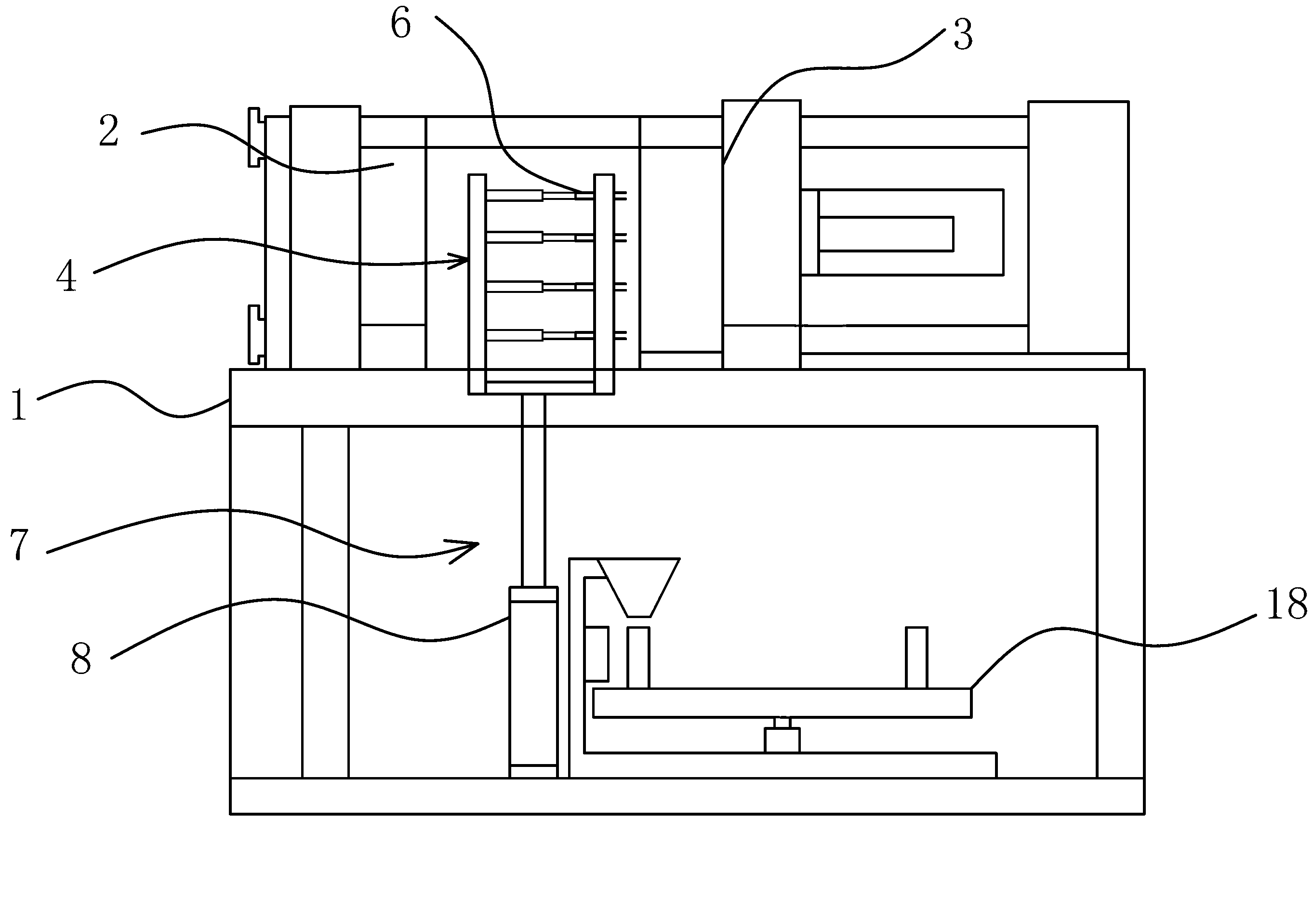
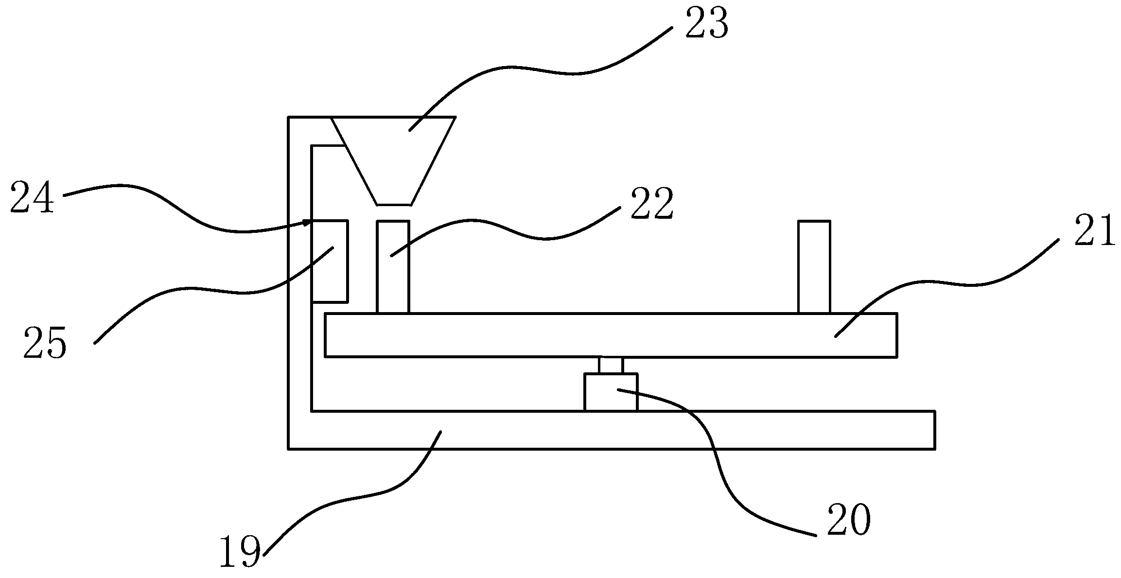
[0031] Such as figure 1 As shown, the injection molding machine includes a machine base 1. A fixed mold plate 2 and a movable mold plate 3 are provided on the machine base 1. The fixed mold plate 2 and the movable mold plate 3 are connected by tie rods, and the movable mold plate 3 and the fixed mold plate 2 are closed to form several The mold cavity of the plastic bottle cap, and when the plastic bottle cap is formed, the opening of the plastic bottle cap faces outward.

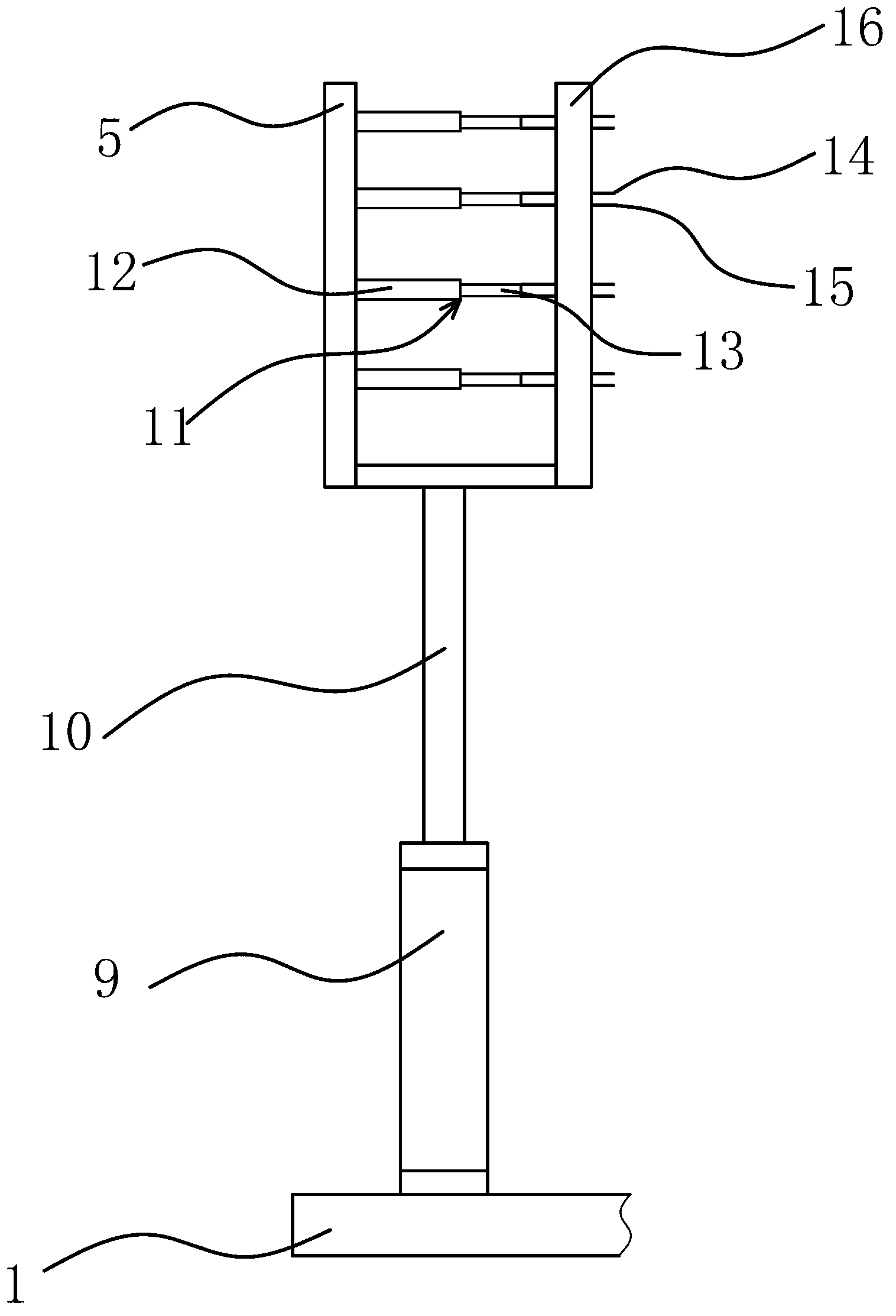
[0032] Such as figure 1 , figure 2 As shown, the injection molding machine also includes a pick-up device 4, the pick-up device 4 includes a pick-up board 5, the pick-up board 5 is provided with a clamping structure 6 capable of fixing or loosening plastic bottle caps, and the frame is fixed. There is a lifting mechanism 7 capable of driving the pickup plate 5 to move up and down to and fro. The lifting mechanism 7 in this embodiment includes several cylinders 8 arranged in the vertical di...

Example Embodiment

[0036] Embodiment two:

[0037] Such as Figure 4 , Figure 5 As shown, this embodiment is roughly the same as the first embodiment. The difference is that the outer end of the piston rod 10 in this embodiment is provided with a fixing seat 26, and the fixing seat 26 is provided with a cylinder 27 along the horizontal direction. , Cylinder three 27 includes cylinder block three and piston rod three, the inner end of piston rod three is inserted in cylinder block three and can make telescopic reciprocating movement, the outer end of piston rod three is fixed on the picking plate 5, the picking plate 5 A cylinder four 28 is arranged in the horizontal direction. The cylinder four 28 includes a cylinder block four and a piston rod four. The inner end of the piston rod four is inserted into the cylinder block four and can be telescopic and reciprocating. The outer end of the piston rod four is fixed There is a baffle 29 parallel to the picking board 5, the clamping structure 6 includ...


PUM


Abstract

The invention provides an injection molding machine for producing plastic bottle caps, belonging to the technical field of moulds and solving the technical problems of poor running stability and the like of the injection molding machine in the prior art. The injection molding machine comprises a base, wherein a fixed mould plate and a movable mould plate are arranged on the base and are connected through a pull rod, and can form a plurality of mould cavities used for forming the plastic bottle caps after getting close, and after the plastic bottle caps are formed, openings of the plastic bottle caps are outwards arranged. The injection molding machine also comprises a piece taking device, wherein the piece taking device comprises a piece taking plate, a clamping structure capable of fixing or loosening the plastic bottle caps is arranged on the piece taking plate, a lifting mechanism capable of driving the piece taking member to go up and down circularly is fixedly arranged on a rack, a holding frame used for holding the plastic bottle caps is arranged on the rack, and a demoulding detection device used for detecting whether the plastic bottle caps drop from the mould cavities completely is arranged on the holding frame. The injection molding machine has the advantages of good running stability and the like.

Description

technical field [0001] The invention belongs to the technical field of moulds, and relates to an injection molding machine for producing plastic bottle caps. Background technique [0002] Injection molding machine is also known as injection molding machine or injection machine. It is the main molding equipment for making thermoplastics or thermosetting materials into various shapes of plastic products with plastic molding molds. Injection molding machine usually consists of injection system, clamping system, transmission system, electrical control system, heating and cooling system, safety monitoring system and so on. The function of the injection system is to heat and plasticize a certain amount of plastic within a specified time in a cycle of the injection molding machine, and then inject it into the mold cavity under a certain pressure and speed. After the injection is completed, the molten material injected into the cavity is kept fixed. The mold clamping system is ma...

Claims


Application Information

Patent Timeline
IPC IPC(8): B29C45/42B29C45/27B29C45/84B29C45/72B29C45/76
Inventor 吴建华
Owner 佛山市顺德区山德塑胶五金有限公司
Why Eureka
Try Eureka