
Vacuum system for vacuum melting

A vacuum system and vacuum smelting technology, which is applied in the field of steelmaking vacuum refining process, can solve the problems of small maintenance workload, difficult supply, large steam consumption, etc., and achieve the effect of saving energy, saving steam consumption, and flexible operation mode

Inactive Publication Date: 2013-09-18
WISDRI ENG & RES INC LTD
View PDF8 Cites 10 Cited by
  • Summary
  • Abstract
  • Description
  • Claims
  • Application Information

AI Technical Summary

Problems solved by technology

[0007] The third method is still an emerging technology, and it is rarely used in domestic steel mills, so it will not be discussed for the time being.
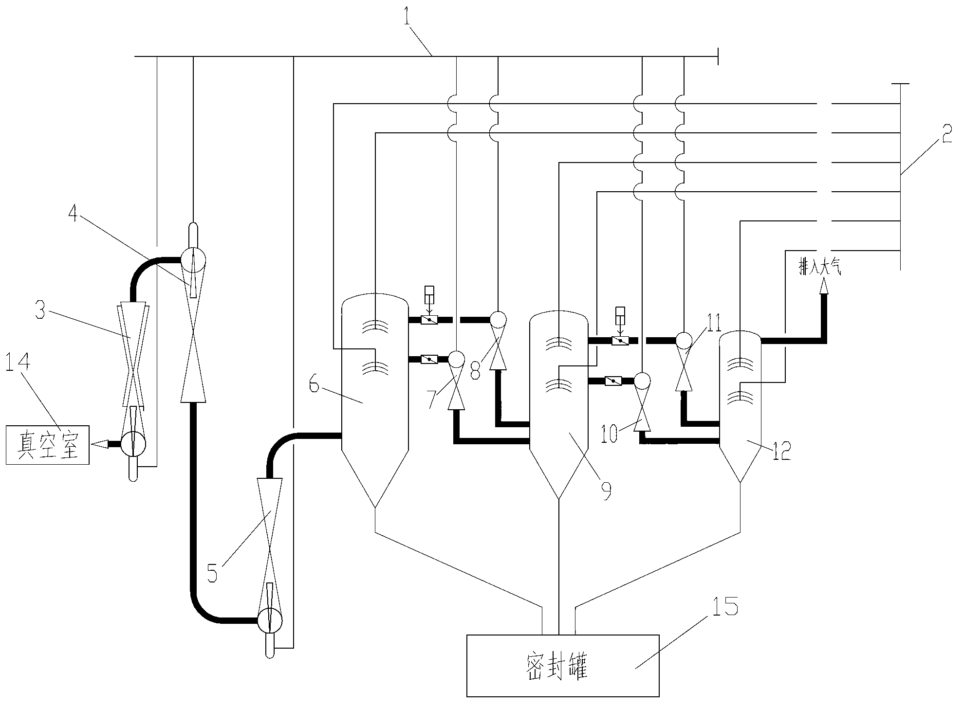
The first method consumes a lot of steam and is very difficult to supply, but the equipment has no mechanical moving parts, the maintenance workload is small, and the operation is very reliable
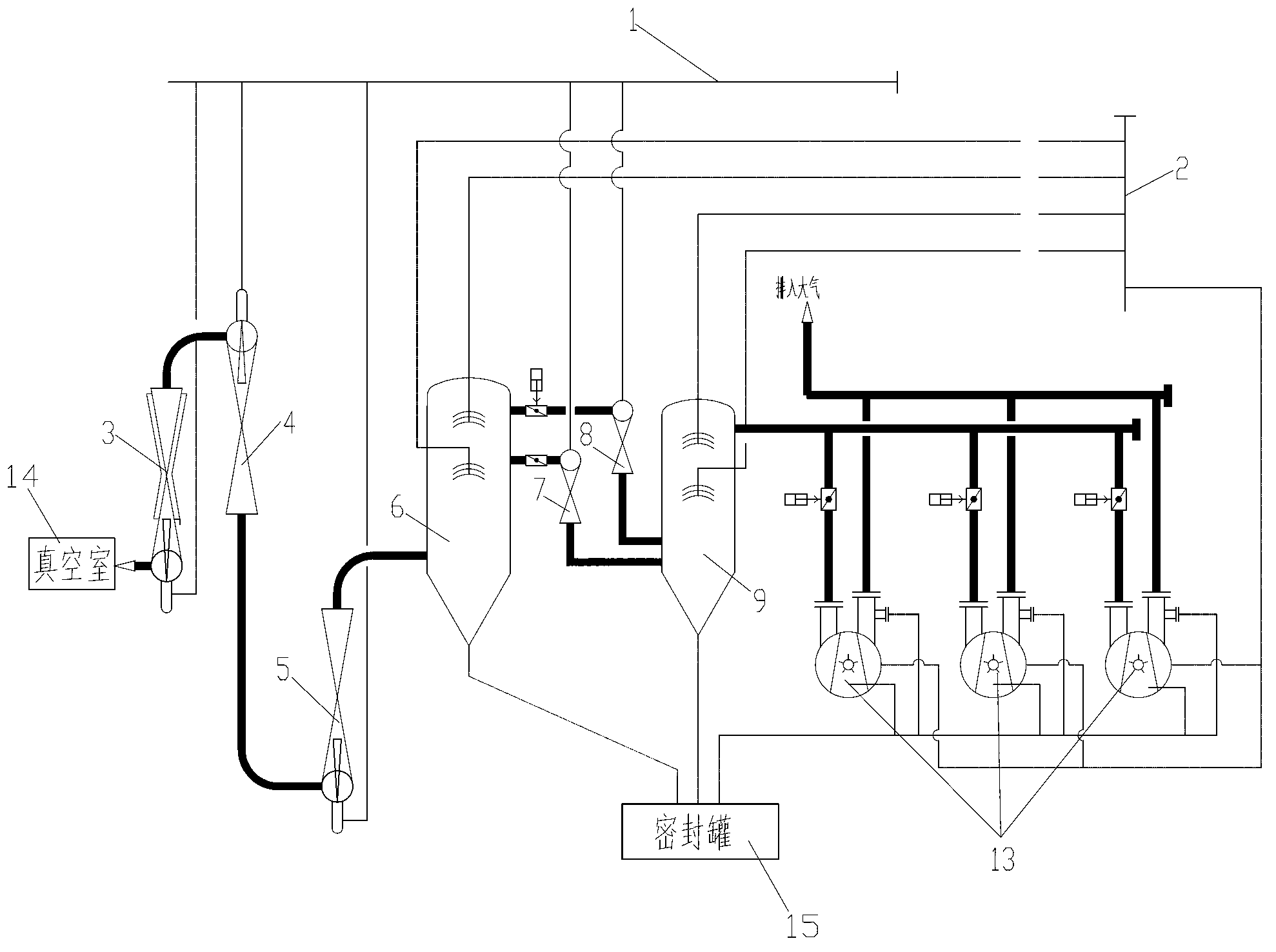
The second method has moderate steam consumption and is equipped with a liquid ring pump, which requires a certain amount of maintenance work and is relatively reliable in operation. However, when the liquid ring pump fails, the vacuum system cannot work normally.

Method used


Image

  • Vacuum system for vacuum melting
  • Vacuum system for vacuum melting
  • Vacuum system for vacuum melting

Examples


Embodiment Construction

[0021] In order to have a clearer understanding of the technical features, purposes and effects of the present invention, the specific implementation manners of the present invention will now be described in detail with reference to the accompanying drawings.

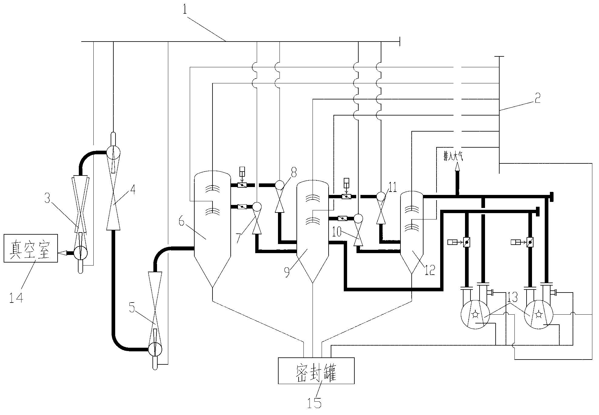
[0022] Such as image 3 As shown, the vacuum system for vacuum smelting of the present invention includes a first-stage steam jet pump 3, a second-stage steam jet pump 4, a third-stage steam jet pump 5, a fourth-stage steam jet pump 7, and a fifth-stage steam jet pump. Jet pump 10 , liquid ring pump group 13 , first stage condenser 6 , second stage condenser 9 and third stage condenser 12 .

[0023] The first-stage steam jet pump 3 is connected with the vacuum chamber 14, the first-stage steam jet pump 3, the second-stage steam-jet pump 4, the third-stage steam-jet pump 5, the fourth-stage steam-jet pump 7 and the fifth-stage steam-jet pump The pumps 10 are connected in series. A first-stage condenser 6 is arranged be...


PUM


Abstract

The invention relates to a vacuum system for vacuum melting. The vacuum system comprises a first-stage steam-jet pump (3), a second-stage steam-jet pump (4), a third-stage steam-jet pump (5), a fourth-stage steam-jet pump (7), a fifth-stage steam-jet pump (10), a first-stage condenser (6) and a second-stage condenser (9) which are connected in series with one another, and also comprises a third-stage condenser (12) and a liquid ring pump unit (13), wherein the liquid ring pump unit (13) and the fifth-stage steam-jet pump (10) are connected in parallel between the second-stage condenser (9) and the third-stage condenser (12); and the liquid ring pump unit (13) comprises a plurality of liquid ring pumps which are connected in parallel with one another. The vacuum system provided by the invention runs flexibly and saves energy; and a very practical solution is supplied to improvement of energy conservation and emission reduction of most full-steam-jet-pump vacuum systems in steel factories in China.

Description

technical field [0001] The invention relates to the field of steelmaking vacuum refining technology, more specifically, relates to a vacuum system for vacuum smelting. Background technique [0002] With the development of my country's national economy, the user's demand for steel products continues to expand, and the requirements for steel quality are also increasing. From the perspective of the process itself and experience, vacuum treatment technology including VD and RH has become one of the effective means to expand the product range and improve product quality, and the vacuum system is one of the key equipment. [0003] The vacuum systems of the existing vacuum treatment devices in various domestic steel mills basically have the following three methods: [0004] The first is to use the vast majority of the total steam jet pump vacuum system, such as figure 1 As shown, the all-steam jet pump vacuum system includes a steam distributor 1, a water distributor 2, and a fir...

Claims


Application Information

Patent Timeline
Patent Type & Authority Applications(China)
IPC IPC(8): C21C7/10
Inventor 许海虹李智成剑明王逸名许畅
Owner WISDRI ENG & RES INC LTD
Learn More