Supercharge Your Innovation With Domain-Expert AI Agents!

Venturi tube for steam purge

A venturi tube and fuel steam technology, applied in electrical control, charging system, adding non-fuel substances to fuel, etc., can solve the problems of lower performance of full throttle opening, increase of air volume, and lower engine performance

Active Publication Date: 2018-04-27
FORD GLOBAL TECH LLC
View PDF6 Cites 0 Cited by
  • Summary
  • Abstract
  • Description
  • Claims
  • Application Information

AI Technical Summary

Problems solved by technology

For example, a venturi connected to the engine's intake system can restrict flow, reducing wide-open throttle performance
Also, in this approach, the position of the venturi relative to the throttle can reduce engine performance
For example, if the venturi is placed in the intake system downstream of the throttle, it increases the amount of air downstream of said throttle, which can lead to reduced transient torque response, especially in turbocharged engines Reduced response

Method used


Image

  • Venturi tube for steam purge
  • Venturi tube for steam purge
  • Venturi tube for steam purge

Examples


Embodiment Construction

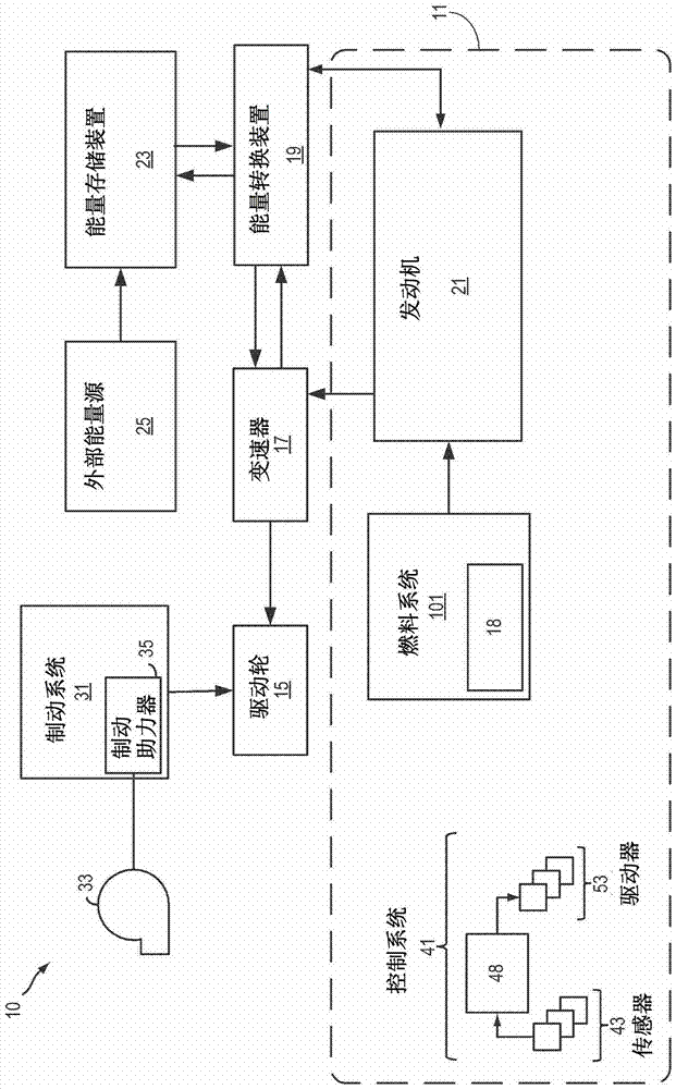
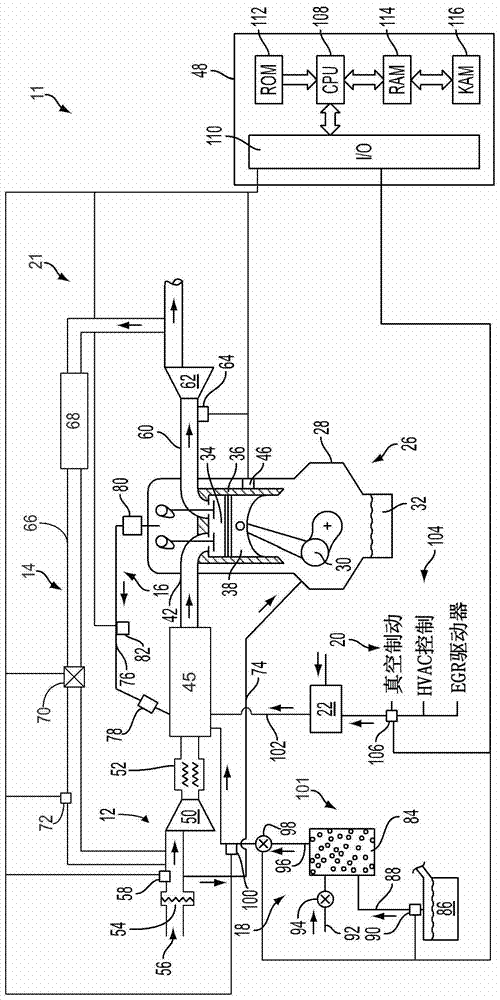
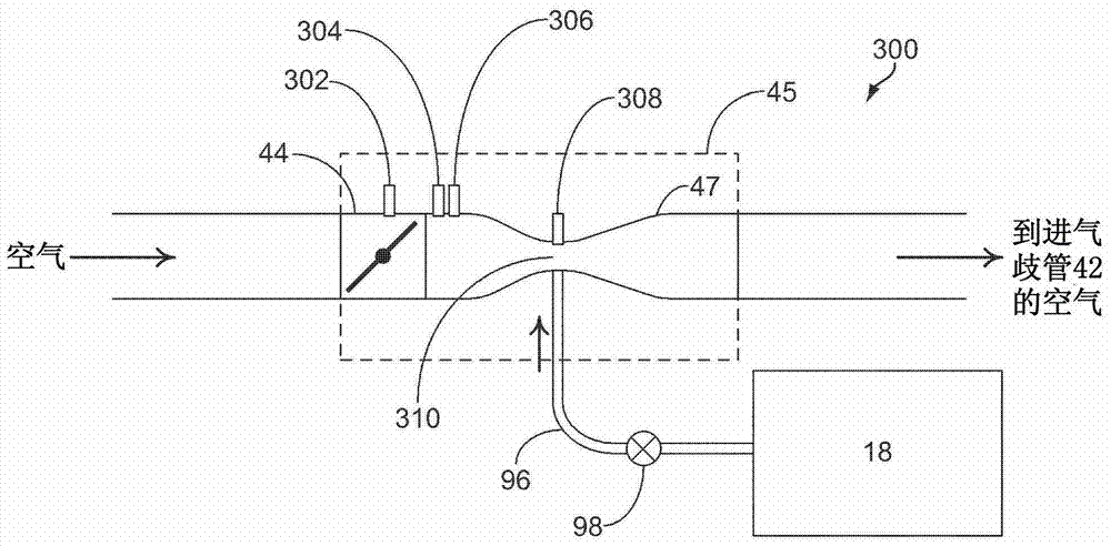
[0027] The following description relates to systems and methods for operating an engine with a fuel vapor purge system, such as figure 1 with figure 2 system shown. Such as Figure 3 to Figure 5 As shown, a venturi or aspirator can be placed in the intake system of the engine adjacent to the throttle, and a fuel vapor purge system can be connected to the venturi so that it can be used during a fuel purge event the resulting vacuum. Such as Figure 6 to Figure 7 As shown, various methods may be used to purge fuel from the fuel vapor purge system using the vacuum created by the venturi. Also, in response to engine operating conditions such as Figure 8 to Figure 11 The throttle shown adjusts to meet torque demand while still providing vacuum to the fuel vapor purge system.

[0028] now refer to figure 1 , which schematically shows an example vehicle with an engine. In some examples, such as figure 1 As shown, the vehicle is a hybrid electric vehicle (HEV) and may inclu...


PUM


Abstract

This invention relates to venturi tubes for steam purging. Systems and methods are provided for an engine including a venturi connected in an engine intake system. In one example method, a method of controlling operation of an engine having a fuel vapor purge system includes directing intake air through a first throttle valve and a venturi arranged in a bypass line at connecting upstream and downstream of a second throttle valve in the intake duct adjacent to the engine intake duct; and delivering a flow of fuel vapor from the fuel vapor purge system to the inlet of the venturi in response to operating conditions.

Description

Background technique [0001] Evaporative emissions control systems capture fuel vapors in an activated carbon canister, such as when parked, and then burn the vapors in the engine when the vehicle is running. In some approaches, the vacuum created in the engine intake manifold is used to pull air through the activated carbon canister to purge the fuel therein. In some examples, such fuel vapor purging systems may be used in engines that include features for increasing fuel economy, such as via variable camshaft timing, variable valve lift, engine downsizing (e.g. EcoBoost) and (e.g. in Hybrid Electric Vehicles (HEV)) hybridization and more. [0002] However, this method of increasing fuel economy reduces the amount of vacuum in the intake manifold, and / or reduces the frequency at which vacuum is available, thus reducing the amount of vacuum available to purge fuel vapors from the fuel vapor purge system . Also, in some examples, if more purge vacuum is required in this appro...

Claims


Application Information

Patent Timeline
Patent Type & Authority Patents(China)
IPC IPC(8): F02M25/08
CPCF02D41/0002F02D41/004F02D41/0087F02D41/042F02M25/08F02M25/0872Y02T10/40F02D41/003F02D41/0032F02D41/0045
Inventor T·G·莱昂内
Owner FORD GLOBAL TECH LLC
Features
  • R&D
  • Intellectual Property
  • Life Sciences
  • Materials
  • Tech Scout
  • Unparalleled Data Quality
  • Higher Quality Content
  • 60% Fewer Hallucinations
Learn More