Centrifugal fan

A technology of centrifugal fans and blades, which is applied to components of pumping devices for elastic fluids, non-variable pumps, machines/engines, etc. It can solve the problems that it is difficult to promote air circulation and improve air volume characteristics, and achieve Excellent air volume characteristics

Active Publication Date: 2013-09-18
NIDEC CORP
View PDF6 Cites 8 Cited by
  • Summary
  • Abstract
  • Description
  • Claims
  • Application Information

AI Technical Summary

Problems solved by technology

Therefore, it is difficult to promote the circulation of air to the outer side in the circumferential direction (exhaust port side)
Therefore, it is difficult to improve the air volume characteristics

Method used


Image

  • Centrifugal fan
  • Centrifugal fan
  • Centrifugal fan

Examples


Embodiment Construction

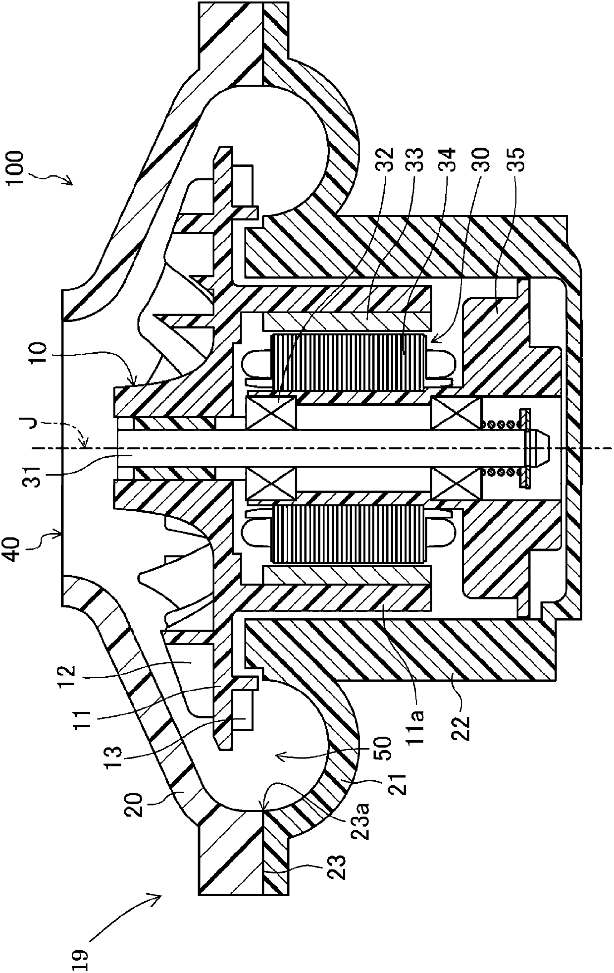
[0019] Hereinafter, embodiments of the present invention will be described in detail with reference to the drawings. In addition, in the description of this embodiment, the direction parallel to the rotation axis is referred to as "axial direction", the direction perpendicular to the rotation axis is referred to as "radial direction", and the direction toward the circumference of the rotation axis is referred to as "radial direction". Called "peripheral". Then, the shape and positional relationship of each part will be described with the direction along the axial direction being the up-down direction and the impeller side being up with respect to the motor. In addition, the present invention is not limited to the following embodiments. Appropriate changes can be made without departing from the effects achieved by the present invention. And it can also be combined with other embodiments.

[0020] figure 1 It is a cross-sectional view which schematically shows the structure ...


PUM


Abstract

A centrifugal fan includes an impeller arranged to rotate about a rotation axis, a motor arranged to rotate the impeller, and a case arranged to accommodate the impeller and the motor. The case includes an upper case, a lower case, and a joint portion at which the upper and lower cases are fixed to each other. An interior of the case includes a first annular space positioned radially outward of the motor. The first annular space includes a second annular space defined by a portion of a space defined by an annularly continuous collection of imaginary circles each of whose diameter is the shortest distance between an inner circumferential edge of the joint portion and a radially outermost circumferential portion of a motor accommodating portion and each of which touches the inner circumferential edge of the joint portion.

Description

technical field [0001] The present invention relates to a centrifugal fan with high static pressure. Background technique [0002] Conventionally, a centrifugal fan for the purpose of increasing the static pressure is known. [0003] For example, US Patent Publication No. 2009 / 0301485 discloses a blower with a shroud on the upper part of the impeller. [0004] Furthermore, Japanese Patent Publication No. 2005-510663 discloses a turbine having an annular compression chamber communicating with the compression chamber. [0005] In the specification of U.S. Patent Publication No. 2009 / 0301485, by providing a shroud above the impeller, the gas flowing into the lower portion of the impeller from the suction port is suppressed from flowing backward toward the suction port side. As a result, the wind resistance of the wind tunnel portion is increased, and the static pressure is increased. [0006] However, to increase the static pressure, it is necessary to increase the wind resi...

Claims


Application Information

Patent Timeline
Patent Type & Authority Applications(China)
IPC IPC(8): F04D29/42F04D29/28F04D29/30
CPCF04D17/02F04D23/008F04D17/16
Inventor 寺本拓矢小西敦生丰岛弘祥平山正士
Owner NIDEC CORP
Why Eureka
Try Eureka