Straight tube-shaped light-emitting diode (LED) lamp

A technology of LED lamps and straight tubes, applied in lighting devices, cooling/heating devices of lighting devices, light sources, etc., can solve the problems of poor heat dissipation of straight tube lamps and complicated manufacturing processes, and achieve simple manufacturing processes and extended The effect of improving the service life and improving the efficiency of heat dissipation

Inactive Publication Date: 2013-09-18
SUZHOU MONT LIGHTING
View PDF6 Cites 11 Cited by
  • Summary
  • Abstract
  • Description
  • Claims
  • Application Information

AI Technical Summary

Problems solved by technology

[0004] The purpose of the present invention is to provide a straight tube LED lamp, which solves the problems of poor heat dissipation and relatively complicated manufacturing process of the existing straight tube lamps

Method used


Image

  • Straight tube-shaped light-emitting diode (LED) lamp
  • Straight tube-shaped light-emitting diode (LED) lamp
  • Straight tube-shaped light-emitting diode (LED) lamp

Examples


Embodiment 1

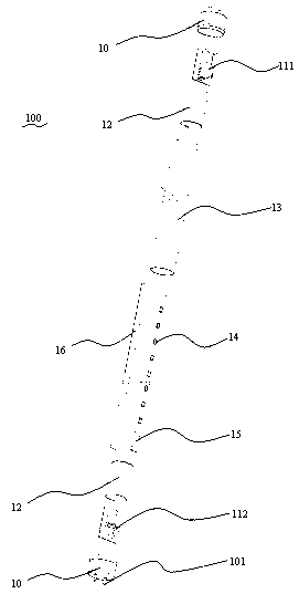
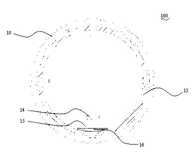
[0021] refer to figure 1 as shown, figure 1 As a three-dimensional exploded view of this specific embodiment, the LED lamp 100 of the present invention includes: a lamp holder 10, a power supply 11, a straight tube lampshade 13, and an LED lighting module 14, wherein the lamp holder 10 is fastened to both ends of the straight tube lampshade 13, specifically , an annular groove (not shown) corresponding to the diameter of the straight tube lampshade 13 can be provided inside the lamp cap 10, and the straight tube lampshade 13 protrudes into the annular groove so as to be fixedly connected with the lamp cap 10, and at the same time In order to make the connection between the lamp cap 10 and the straight tube lampshade 13 more firm, the lamp cap 10 and the straight tube lampshade 13 are bonded together with an adhesive, and the adhesive can be silica gel.

[0022] An electric contact 101 protrudes from the lamp cap 10 , and the power supply 11 is electrically connected to the la...

Embodiment 2

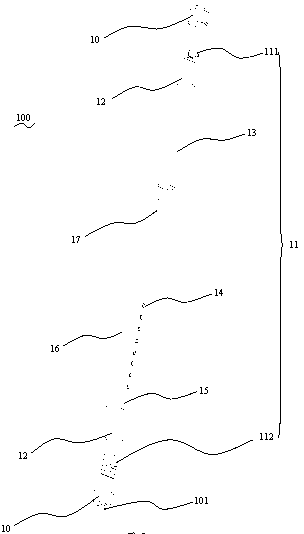
[0030] refer to image 3 as shown, image 3 It is a three-dimensional exploded view of this specific embodiment, and the general idea of ​​the design of this specific embodiment is generally the same as that of Embodiment 1. The differences between this embodiment and Embodiment 1 are mainly introduced now. The difference between this embodiment and the first embodiment is that the LED lamp 100 further includes a metal foil plate 17 located on the inner wall of the straight tube lampshade 13 , and the substrate 15 carrying the LED light emitting module 14 is located on the metal foil plate 17 . Thus, the LED light-emitting module 14, the substrate 15, and the metal foil plate 17 form a layered structure. Specifically, the base plate 15 and the metal foil plate 17 can be fixed together by a heat-conducting glue 16, and the heat-conducting glue 16 can be any material with heat conduction and fixing functions, such as a heat-conducting double-sided adhesive or a heat-conducting ...


PUM


Abstract

The invention provides a straight tube-shaped light-emitting diode (LED) lamp. The lamp comprises a lamp holder, a power supply and a straight tube lampshade, wherein the lamp holder is buckled with the two ends of the straight tube lampshade, and the power supply is electrically connected with the lamp holder; and the straight tube-shaped lamp further comprises an LED light-emitting module and a substrate, wherein the substrate bears the LED light-emitting module and is fixedly arranged on the inner wall of the straight tube lampshade through a bonding material. The internal heat dissipation structure of the straight tube-shaped lamp is improved, so that the heat which is generated by the light emitting of the LED light-emitting module can be dissipated in time, the heat dissipation efficiency is improved, the LED light-emitting module is protected, and the service life of the LED light-emitting module is prolonged; and moreover, the lamp is simple in production technology, and the production cost of the straight tube-shaped LED lamp is lowered.

Description

technical field [0001] The invention relates to a lighting fixture, in particular to a straight tube LED lamp. Background technique [0002] For a long time, fluorescent lamps have been the more commonly used lighting fixtures in daily lighting places, occupying a larger share in the market. However, traditional fluorescent lamps use voltage to heat the filament to vaporize mercury-containing compounds and excite phosphors on the wall of the lamp tube to emit light. This method not only consumes a lot of energy, but is also extremely environmentally unfriendly, because mercury is a toxic heavy metal. If the used fluorescent tubes are discarded, it will cause certain pollution to the environment. According to this, LED fluorescent lamps appeared later. LED fluorescent lamps use light-emitting diodes instead of gas to emit light, and do not contain mercury. At the same time, LED fluorescent lamps reduce energy consumption and are more environmentally friendly. However, the c...

Claims


Application Information

Patent Timeline
Patent Type & Authority Applications(China)
IPC IPC(8): F21S2/00F21V29/00F21V19/00F21V17/10F21Y101/02F21V29/503
Inventor 张迎春张臣
Owner SUZHOU MONT LIGHTING
Why Eureka
Try Eureka