Check patentability & draft patents in minutes with Patsnap Eureka AI!

A flexible joint angle sensor

An angle sensor, flexible joint technology, applied in the direction of instruments, measuring devices, etc., can solve the problems of complex system, large detection error, limited application environment, etc., and achieve the effects of high measurement accuracy, simple and compact structure, and wide application fields.

Active Publication Date: 2016-02-10
HARBIN INST OF TECH
View PDF3 Cites 0 Cited by
  • Summary
  • Abstract
  • Description
  • Claims
  • Application Information

AI Technical Summary

Problems solved by technology

[0003] The purpose of the present invention is to solve the problems that the existing methods of measuring human body posture usually adopt inertial sensor detection and video detection. These two methods have the problems of complex system, large detection error and limited application environment, and provide a flexible joint angle sensor

Method used


Image

  • A flexible joint angle sensor
  • A flexible joint angle sensor
  • A flexible joint angle sensor

Examples


specific Embodiment approach 1

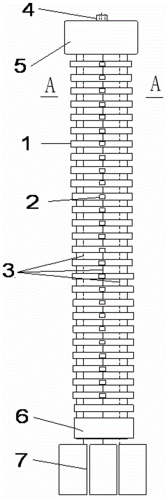
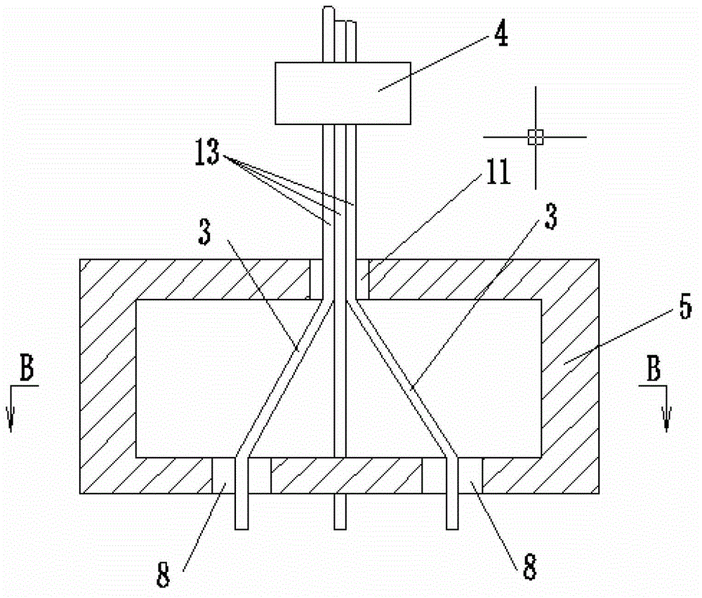
[0008] Embodiment 1: Combining Figure 1 to Figure 6 Illustrating this embodiment, this embodiment includes a flexible bellows 1, an upper fixing block 4, a fixing ring 5, a lower fixing block 6, a displacement sensor 7, three steel wires 3 and three steel wire sliding tracks. The upper end of the flexible bellows 1 is connected to the The fixing ring 5 is connected, the lower end of the flexible bellows 1 is connected with the lower fixing block 6, and each wave crest on the outer surface of the flexible bellows 1 is evenly distributed with three steel wire sliding tracks 2 along the circumference. The steel wire sliding track 2 on the wave crest is set up and down one by one, the fixing ring 5 is a hollow structure, a central hole 11 is arranged at the center of the upper end face of the fixing ring 5, and three upper through holes 8 are arranged on the lower end face of the fixing ring 5 , the lower fixing block 6 is provided with three lower through holes 9, the steel wire...

specific Embodiment approach 2

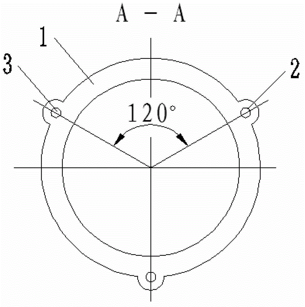
[0009] Specific implementation mode 2: Combining figure 2 Illustrating this embodiment, the three upper through holes 8 on the fixing ring 5 of this embodiment are evenly distributed along the circumference. This is designed so that the three steel wires 3 are uniformly stressed. Other components and connection relationships are the same as in the first embodiment.

specific Embodiment approach 3

[0010] Specific implementation three: combination image 3 , Figure 4 , Figure 5 , Image 6 Describing this embodiment, the three lower through holes 9 and the three upper through holes 8 in this embodiment are disposed in a one-to-one manner. This design is convenient for the steel wires 3 to pass through, so that the three steel wires 3 are evenly stressed. Other compositions and connection relationships are the same as in the second embodiment.


PUM


Abstract

The invention discloses a flexible joint angle sensor, and relates to a joint angle sensor. The flexible joint angle sensor is used for solving the problem of high detection errors of an inertia sensor detection method and a video detection method which are used as human posture measuring means at present. The flexible joint angle sensor is characterized in that the upper end of a flexible corrugated pipe is connected with a fixing ring, the lower end of the flexible corrugated pipe is connected with a lower fixing block, three steel wire sliding tracks are circumferentially and uniformly distributed at each crest on the flexible corrugated pipe, the multiple steel wire sliding tracks which are arranged along the direction of a generating line of the surface of the flexible corrugated pipe are vertically opposite to one another, the fixing ring is of a hollow structure, a center hole is formed in the center of the upper end surface of the fixing ring, three upper through holes are formed in the lower end surface of the fixing ring, three lower through holes are formed in the lower fixing block, a steel wire harness comprising three steel wires is arranged in the center hole, the upper end of the steel wire harness penetrates an upper fixing block, and the lower ends of the three steel wires respectively penetrate the three upper through holes, pass through each three corresponding steel wire sliding tracks, respectively penetrate the three lower through holes and then are connected with displacement sensors. The flexible joint angle sensor is used for measuring postures of organisms.

Description

technical field [0001] The invention relates to an attitude detection sensor, in particular to a flexible joint angle sensor. Background technique [0002] Existing human body attitude measurement methods usually use inertial sensor detection and video detection methods. The inertial devices use several acceleration sensors and gyroscopes to measure joint angles, and the measurement systems and data processing are complicated. Its long-term detection will cause a large cumulative error and reduce the measurement accuracy; it is not suitable for attitude detection in dynamic environments (such as running cars, airplanes), and any dynamic changes in the external environment will lead to obvious parameter distortion and is not applicable Measured at rest attitude. This method is mainly aimed at short-term continuous motion measurement in a static environment. At this stage, the accuracy of anthropometric measurement is about 2-3 degrees. The 3D motion data captured by video d...

Claims


Application Information

Patent Timeline
Patent Type & Authority Patents(China)
IPC IPC(8): G01B21/22
Inventor 全威王华张瞫刘昕
Owner HARBIN INST OF TECH
Features
  • R&D
  • Intellectual Property
  • Life Sciences
  • Materials
  • Tech Scout
  • Unparalleled Data Quality
  • Higher Quality Content
  • 60% Fewer Hallucinations
Learn More