Eureka AIR delivers breakthrough ideas for toughest innovation challenges, trusted by R&D personnel around the world.

Mems capacitive pressure sensor

A pressure sensor and sensor technology, applied in the direction of fluid pressure measurement using capacitance changes, fluid pressure measurement through electromagnetic components, elastic deformation gauge fluid pressure measurement, etc.

Active Publication Date: 2013-09-18
希奥检测有限公司
View PDF6 Cites 51 Cited by
  • Summary
  • Abstract
  • Description
  • Claims
  • Application Information

AI Technical Summary

Problems solved by technology

[0017] Currently, there is no way to perform self-calibration and correct for signal drift in an industrial environment

Method used


Image

  • Mems capacitive pressure sensor
  • Mems capacitive pressure sensor
  • Mems capacitive pressure sensor

Examples


Embodiment Construction

[0060] The present invention provides a pressure sensor capable of performing self-calibration and correcting for signal drift. The pressure difference between the external medium and the cavity is sensed by measuring the deflection of the membrane using a capacitive readout method. There are two ways of implementing the invention. One way involves the use of an integrated Pirani sensor and the other way involves the use of an integrated resonator, used as a reference pressure sensor.

[0061] Since its invention in 1906, the Pirani pressure gauge has been widely used for vacuum measurement. A heating wire with a high temperature coefficient of resistance is placed under vacuum. A wire (whose resistance is proportional to its temperature,) forms one arm of a balanced Wheatstone bridge. Gas molecules collide with the wire, transferring heat from the wire and unbalancing the bridge relative to a reference state. Since the frequency of molecular collisions is proportional to ...


PUM

PropertyMeasurementUnit
pressureaaaaaaaaaa
thicknessaaaaaaaaaa
heightaaaaaaaaaa

Abstract

A pressure sensor measures pressure by measuring the deflection of a MEMS membrane using a capacitive read-out method. There are two ways to implement the invention. One involves the use of an integrated Pirani sensor and the other involves the use of an integrated resonator, to function as a reference pressure sensor, for measuring an internal cavity pressure.

Description

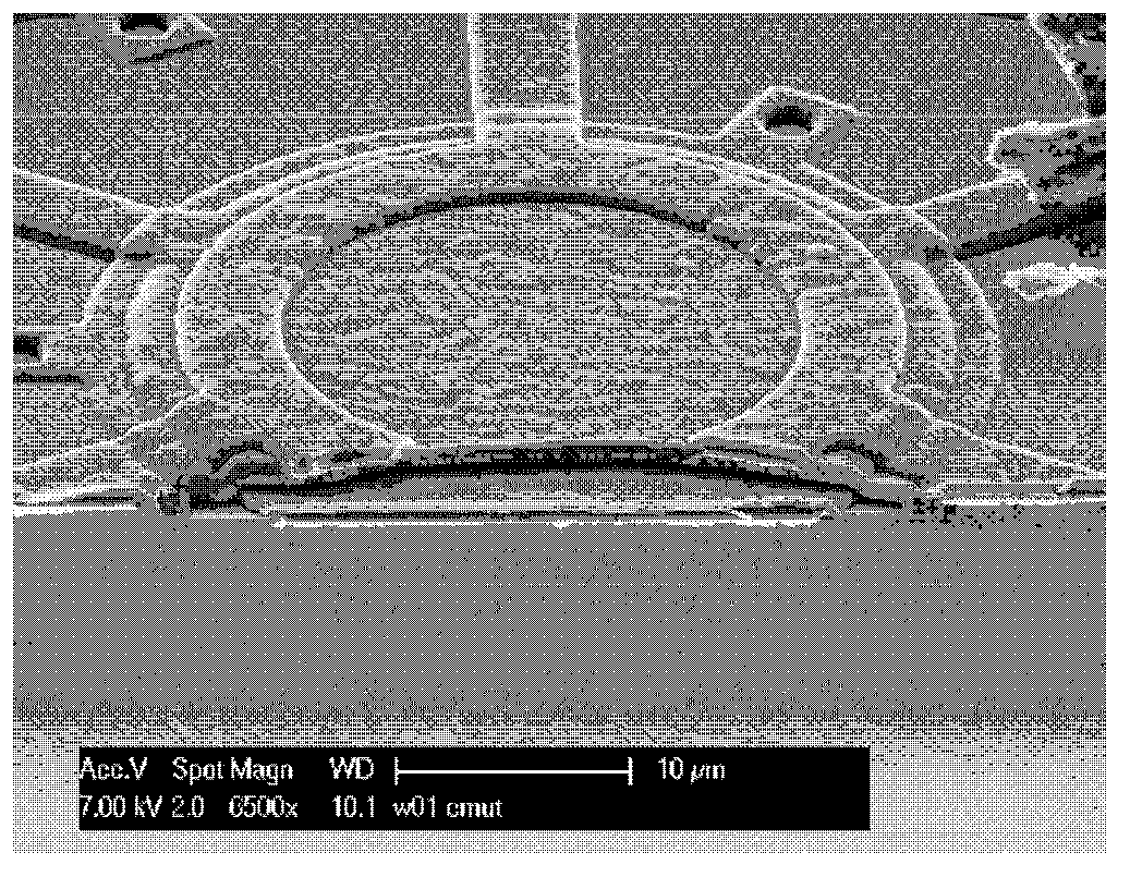
technical field [0001] The present invention relates to MEMS capacitive pressure sensors. Background technique [0002] MEMS pressure sensors typically have piezoresistive or capacitive readout and are well known in the art. [0003] exist figure 1 A SEM cross-section of an example of a capacitive MEMS pressure sensor is shown in . The figure shows the device after sacrificial layer etching and closing of the etched holes with a 2 μm thick PECVD SiN film as one of the last thin film fabrication steps. [0004] The sensor has a suspended SiN film. The cavity under the SiN thin film is hermetically sealed by using the PEVCD SiN process. The final device performance is largely determined by the geometric, physical, mechanical and structural properties of this thin film. The density and composition of the film determine the airtightness, outgassing behavior and internal stresses. The stress together with the SiN thickness determines the stiffness of the membrane and thus t...

Claims


Application Information

Patent Timeline
Patent Type & Authority Applications(China)
IPC IPC(8): G01L9/00
CPCG01L9/0073G01L15/00G01L21/12G01L21/22G01L27/002Y10T29/49117G01L9/0045G01L13/025G01L9/12G01L1/14G01L1/142G01L7/08G01L7/088G01L9/0041G01L9/0072G01L9/125G01L13/026
Inventor 威廉·弗雷德里克·亚德里亚内斯·贝什林马丁·古森思约瑟夫·托马斯·马丁内斯·范贝克皮特·杰勒德·斯蒂内肯奥拉夫·温尼克
Owner 希奥检测有限公司
Why Eureka
Eureka Blog
Learn More