Feeding device for fasteners

A technology for feeding devices and fasteners, which is applied to conveyor control devices, conveyor objects, transportation and packaging, etc., can solve the problems of complex and heavy mechanism, inconvenient use, and high cost, and achieve high control accuracy, reduce wear, and weight. light effect

Active Publication Date: 2013-09-18
RITAI SHANGHAI AUTO STANDARD COMPONENT
View PDF5 Cites 3 Cited by
  • Summary
  • Abstract
  • Description
  • Claims
  • Application Information

AI Technical Summary

Problems solved by technology

[0003] The existing fastener feeding equipment is designed for large-scale machine tools, the mechanism is complex and heavy, and it is ve

Method used


Image

  • Feeding device for fasteners
  • Feeding device for fasteners
  • Feeding device for fasteners

Examples


Example Embodiment

[0024] Example one:

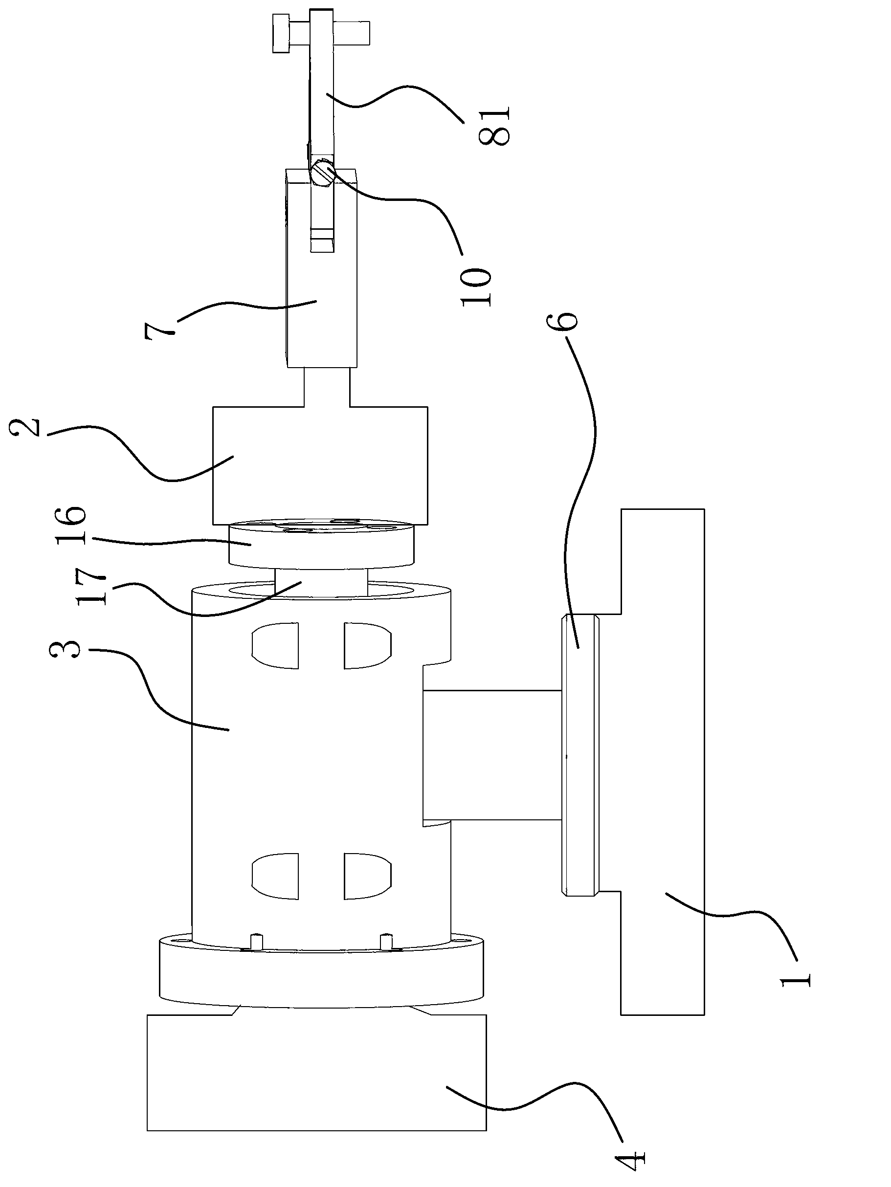
[0025] Such as figure 1 As shown, a feeding device for fasteners includes a base 1, on which a telescopic cylinder 2 and a shaft sleeve 3 are provided, and the end of the piston rod of the telescopic cylinder 2 is provided for clamping and tightening. Firmware clamping mechanism, the shaft sleeve 3 is provided with a bearing, the outer ring of the bearing is fixed on the inner wall of the shaft sleeve 3, and the cylinder block of the telescopic cylinder 2 is fixed on the inner ring of the bearing , The axis line of the bearing is parallel to the telescopic direction of the piston rod of the telescopic cylinder 2, the sleeve 3 is also provided with a rotating mechanism that can drive the inner ring of the bearing to rotate, and the base 1 is also A second rotating mechanism capable of driving the shaft sleeve 3 to rotate in the horizontal direction is provided.

[0026] The first rotating mechanism includes a PLC programmable controller and a swing cylinder 4....

Example Embodiment

[0038] Embodiment two:

[0039] The contents in this embodiment are roughly the same as those in the first embodiment, but the difference is that the rotating mechanism in the first embodiment includes a PLC programmable controller and a swing cylinder 4. The PLC programmable controller is fixed in On the base 1, the cylinder block of the swing cylinder-4 is fixed on the sleeve 3, the output shaft of the swing cylinder-4 is fixedly connected with the inner ring of the bearing, and the The oscillating cylinder 4 is connected to the PLC programmable controller through the line 1. The second rotating mechanism is the second swing cylinder 6. The cylinder of the second swing cylinder 6 is fixed on the base 1, the output shaft of the second swing cylinder 6 is fixed on the above-mentioned sleeve 3, and the second swing cylinder The output shaft of the second 6 is perpendicular to the axial direction of the sleeve 3, and the second 6 oscillating cylinder is connected to the above-ment...


PUM


Abstract

The invention provides a feeding device for fasteners and belongs to the technical field of machines. According to the feeding device, the technical problems that existing feeding devices are complex in structure, low in delivery efficiency, large in occupied space and the like are solved. The feeding device for the fasteners comprises a base, wherein a telescopic cylinder and a shaft sleeve are arranged on the base, a clamping mechanism which is used for clamping the fasteners is arranged on the end portion of a piston rod of the telescopic cylinder, a bearing is arranged inside the shaft sleeve, an outer ring of the bearing is fixed on the inner wall of the shaft sleeve, a cylinder body of the telescopic cylinder is fixed on an inner ring of the bearing, an axis line of the bearing is parallel with the telescopic direction of the piston rod of the telescopic cylinder, a first rotating mechanism which can drive the inner ring of the bearing to rotate is arranged on the shaft sleeve, and a second rotating mechanism which can drive the shaft sleeve to rotate in the horizontal direction is also arranged on the base. The feeding device has the advantages of being simple in structure, high in delivery efficiency, small in occupied space and the like.

Description

technical field [0001] The invention belongs to the technical field of machinery and relates to a feeding device, in particular to a feeding device for fasteners. Background technique [0002] Fasteners, also known as standard parts in the market, are a general term for a class of mechanical parts used when two or more parts (or components) are fastened and connected into a whole. It is characterized by a wide variety of specifications, different performances and uses, and a high degree of standardization, serialization, and generalization. Fasteners are the most widely used mechanical basic parts and are in great demand. Screws and bolts are the two most common types of fasteners. Screws and bolts are widely used in various industries, even on aircraft. [0003] Existing fastener feeding equipment is designed to cooperate with large-scale machine tools. The mechanism is complex and heavy, and it is very inconvenient to use. In addition, these feeding equipment can only be...

Claims


Application Information

Patent Timeline
IPC IPC(8): G05B19/05B65G43/08
Inventor 房立君胡俊志李涛
Owner RITAI SHANGHAI AUTO STANDARD COMPONENT
Why Eureka
Try Eureka