Supercharge Your Innovation With Domain-Expert AI Agents!

Pneumatic-controlled smoke detector test device

A smoke detector and test device technology, which is applied in the direction of fire alarms, instruments, and alarms that rely on the effect of smoke/gas, can solve problems such as failure of the fire alarm system, failure of automatic fire alarm in a timely manner, and reduced sensitivity. The effect of improving equipment safety and reliability, avoiding the expansion of fire accidents, and reducing workload

Inactive Publication Date: 2013-09-18
STATE GRID CORP OF CHINA +1
View PDF0 Cites 2 Cited by
  • Summary
  • Abstract
  • Description
  • Claims
  • Application Information

AI Technical Summary

Problems solved by technology

[0003] At present, after the smoke detectors of all fire alarm systems in substations are installed and put into operation on site, they cannot be checked for integrity due to lack of special testing tools. If it is discovered in time, it will cause the fire alarm system in important fire prevention places to fail. When a fire occurs, it will not be able to automatically and timely report to the police, resulting in major fire losses.
[0004] Therefore, there is an urgent need for a special detection test device for smoke detectors in the power grid system, which is used to regularly check and test the smoke detectors to ensure their integrity. The successful development of this smoke detector detection test device can be widely used in hotels, factories, shopping malls, warehouses , Office buildings, hotels, residential buildings, electric power, petrochemical, and other industries, such as on-site detection of fire alarm systems in important places for fire prevention. At present, there is no one in various industries that tests smoke detectors in places where high voltage is strictly prohibited. special tools

Method used


Image

  • Pneumatic-controlled smoke detector test device

Examples


Embodiment Construction

[0011] The present invention is not limited by the following examples, and specific implementation methods can be determined according to the technical solutions of the present invention and actual conditions.

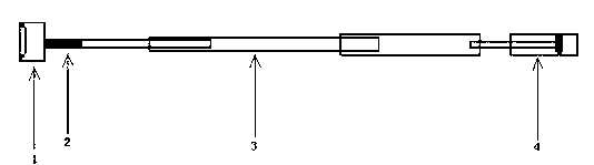
[0012] Example : Such as figure 1 As shown, the air-operated smoke detector detection test device includes an air-controlled switch-type electronic smoke generator 2 and a smoke collection box 1, and the smoke outlet of the air-controlled switch-type electronic smoke generator 2 communicates with the inner cavity of the smoke collection box 1. The gas control switch type electronic smoke generator 2 air inlet communicates with the upper port of the telescopic insulating rod 3 , and the lower port of the telescopic insulating rod 3 communicates with the air outlet of the compressed air cylinder 4 .

[0013] The function of air-operated switch-type electronic smoke generator 2 is to generate smog, in which a lithium battery, an air-operated switch and a heating wire for...


PUM


Abstract

The invention relates to a pneumatic-controlled smoke detector test device comprising a pneumatic-switch type electronic smoke generator and a smoke-collecting box. A smoke outlet of the pneumatic-switch type electronic smoke generator is communicated with an inner cavity of the smoke-collecting box, a smoke inlet of the pneumatic-switch type electronic smoke generator is communicated with an upper end port of a telescopic insulating rod, and an upper end port of the telescopic insulating rod is communicated with a smoke outlet of a pneumatic cylinder. By the aid of the pneumatic-controlled smoke detector test device, safety of a device can be guaranteed and fire accident expanding caused by failure of a fire alarm can be avoided, so that the safety and reliability of the device can be improved. By adopting the lengthened telescopic insulating rod which can withstand high voltage of 220kV, a worker standing on the ground without using a ladder can test a smoke detector of any height, therefore the pneumatic-controlled smoke detector test device simple to operate is applicable to substation utilization at various voltage levels, and working load of testing workers is reduced.

Description

technical field [0001] The invention relates to an air-controlled smoke detector detection test device. Background technique [0002] The fire alarm system of the substation is an important safety system, especially now that all substations are unattended, the fire alarm system is the most important. After a fire occurs, it will automatically alarm in time and notify the personnel to fire and extinguish the fire, so as to minimize the fire loss. Fire alarm The system relies on smoke detectors to detect fires. If the smoke detectors fail or are insensitive, fires cannot be detected in time. Therefore, it is necessary to ensure that the smoke detectors in each important fire protection place of the substation are in good condition. [0003] At present, after the smoke detectors of all fire alarm systems in substations are installed and put into operation on site, they cannot be checked for integrity due to lack of special testing tools. If it is discovered in time, it will ca...

Claims


Application Information

Patent Timeline
IPC IPC(8): G08B29/00G08B17/10
Inventor 顾世峰
Owner STATE GRID CORP OF CHINA
Features
  • R&D
  • Intellectual Property
  • Life Sciences
  • Materials
  • Tech Scout
  • Unparalleled Data Quality
  • Higher Quality Content
  • 60% Fewer Hallucinations
Learn More