Device and method used for dairy cow positioning

A technology of dairy cows and working methods, which is applied in the field of system equipment for auxiliary feeding of dairy cows, can solve problems such as inaccurate calculation results, difficult to complete by one person, and heavy workload, and achieve the goals of saving manpower, high degree of intelligence, and improving work efficiency Effect

Inactive Publication Date: 2013-09-18
SHANDONG UNIV
View PDF3 Cites 8 Cited by
  • Summary
  • Abstract
  • Description
  • Claims
  • Application Information

AI Technical Summary

Problems solved by technology

[0002] At present, in large-scale dairy farms, when searching for a certain cow or counting the number of all cows, it is generally done by manpower. The workload is heavy and it is difficult for one person to complete it. If there is another emergency, there will be more serious consequences.
In addition, due to the relatively large area of ​​the dairy farm, the transmission distance of low-power equipment is limited. If the chips CC2430 and CC2431 are used to transmit data, it will lead to inaccurate calculation results or interruption of transmission.

Method used


Image

  • Device and method used for dairy cow positioning
  • Device and method used for dairy cow positioning

Examples


Embodiment 1

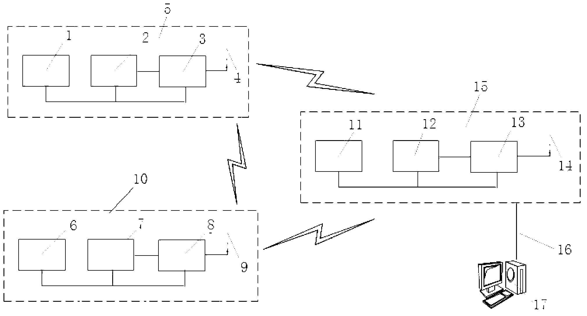
[0047] Embodiment 1 of the present invention such as figure 1 , figure 2 As shown, a device for positioning cows, including PC17, coordinator 15, router 10 and terminal equipment 5, is characterized in that terminal equipment 5 includes single-chip microcomputer 2, wireless transmission module 3, antenna 4 and DC power supply 1, wherein DC The power supply 1 is connected to the wireless transmission module 3 and the single-chip microcomputer 2 respectively, the single-chip microcomputer 2 is connected to the wireless transmission module 3, the wireless transmission module 3 is connected to the antenna 4; the router 10 includes a single-chip computer 7, a wireless transmission module 8, an antenna 9 and a DC power supply 6 , wherein the DC power supply 6 is connected to the wireless transmission module 8 and the single-chip microcomputer 7 respectively, the single-chip microcomputer 7 is connected to the wireless transmission module 8, and the wireless transmission module 8 is...

Embodiment 2

[0052] A method for working with the above-mentioned device, the steps are as follows:

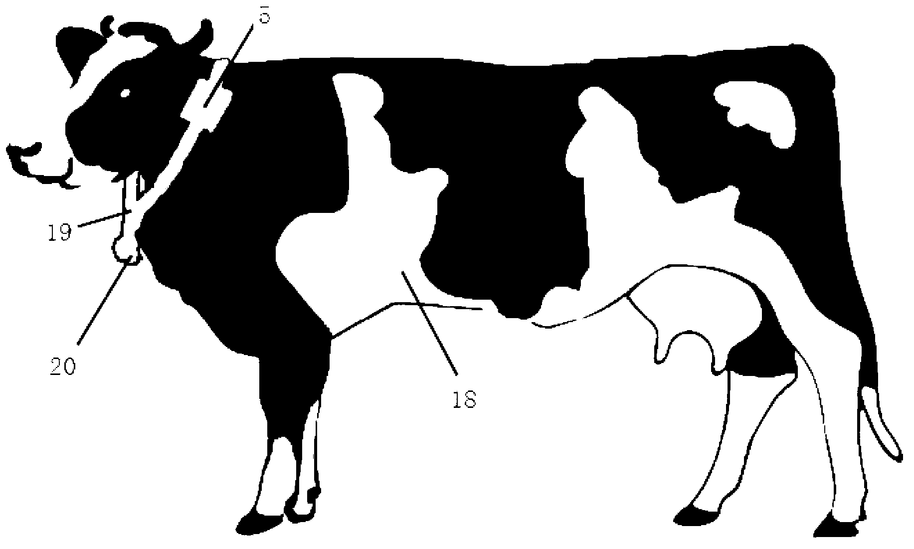
[0053] Distribute and fix multiple routers at different points of the dairy farm, record their positions, put the lanyard with the terminal equipment fixed on the neck of the cow, turn on the power of the coordinator, establish a network, and turn on the power of the router and the terminal equipment in turn , to join the network; the coordinator transmits the received data to the PC, and the PC software finally checks the position of the cow;

[0054] The working method of the coordinator is as follows:

[0055] ① start;

[0056] ②Establish a network;

[0057] ③The coordinator receives the router binding data, router coordinates and ID number, and performs PC display processing;

[0058] ④The coordinator checks whether the data sent by the terminal device is received, if received, it can be displayed on the PC, otherwise repeat step ④;

[0059] The working method of the router, the st...


PUM


Abstract

The invention discloses a device and a method used for dairy cow positioning and belongs to the technical field of automatic positioning of dairy cows. The device comprises a PC (personal computer), a coordinator, a router and terminal equipment, when in use, the terminal equipment is sleeved on necks of the dairy cows through hanging ropes, the coordinator is connected with the PC through a serial port line, the coordinator, the router and the terminal equipment are all connected through wireless communication, the PC, the coordinator, the router and the terminal equipment forms a wireless transmission network of a tree-shaped topological structure, and the wireless transmission network performs data transmission positioning on the dairy cows. The device and the method used for dairy cow positioning have the advantages that the position of a certain dairy cow can be known timely, intelligentization level is high, manpower is saved, convenience is brought to feeding and managing of the dairy cows, and working efficiency is improved.

Description

technical field [0001] The invention relates to a system equipment for assisting in raising dairy cows, in particular to a device and method for locating dairy cows which can know the position of a cow in time, facilitate feeding and management of dairy cows, and improve work efficiency. Background technique [0002] At present, in large-scale dairy farms, when searching for a certain cow or counting the number of all cows, it is generally done by manpower. The workload is heavy and it is difficult for one person to complete it. If there is another emergency, there will be more serious consequences. In addition, due to the relatively large area of ​​the dairy farm, the transmission distance of low-power equipment is limited. If the chips CC2430 and CC2431 are used to transmit data, it will lead to inaccurate calculation results or interruption of transmission. Liu Xinming, Zhang Changli, Li Jianze's research on dairy cow positioning system based on Zigbee technology. China H...

Claims


Application Information

Patent Timeline
Patent Type & Authority Applications(China)
IPC IPC(8): H04W24/00H04W64/00
Inventor 姜威郭庆司陈何孟宁
Owner SHANDONG UNIV
Why Eureka
Try Eureka