Contrast media injector syringe inlet valve system

A technology of injection barrel and inlet valve, which is applied in the field of syringe system and can solve problems such as viscosity reduction and density reduction

Active Publication Date: 2013-09-18
ACIST MEDICAL SYST
View PDF9 Cites 7 Cited by
  • Summary
  • Abstract
  • Description
  • Claims
  • Application Information

AI Technical Summary

Problems solved by technology

Accordingly, some formulations of contrast media contain a reduced amount of imaging material in a given volume of fluid, thereby making it less viscous and less dense

Method used


Image

  • Contrast media injector syringe inlet valve system
  • Contrast media injector syringe inlet valve system
  • Contrast media injector syringe inlet valve system

Examples


Embodiment Construction

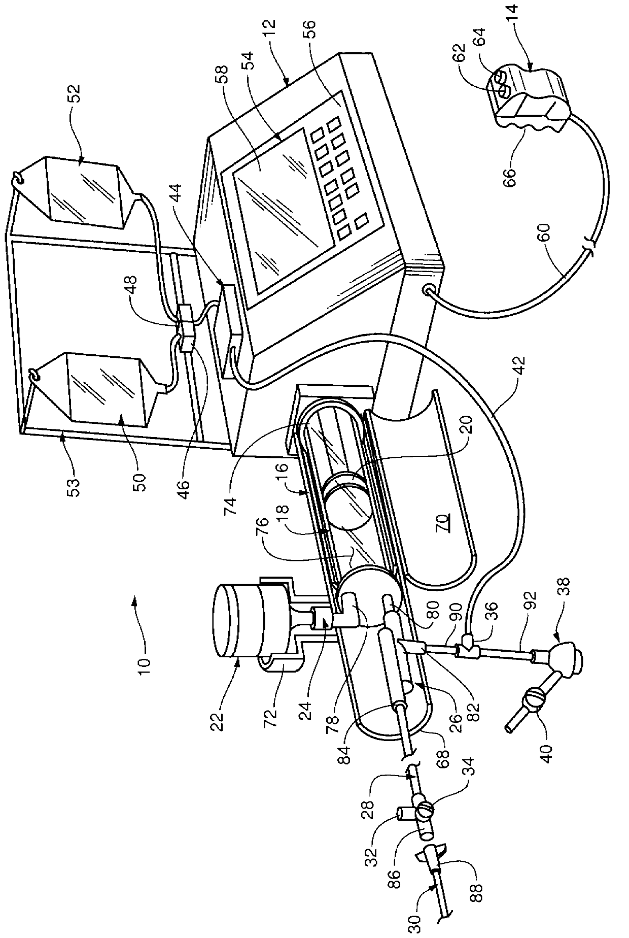
[0029] Various exemplary embodiments are described herein with reference to the drawings, in which like reference numerals describe like elements. References to above, below, horizontal, vertical, front, rear, left, right, etc. shall refer to the orientation of the syringe when properly positioned within the contrast media injector system.

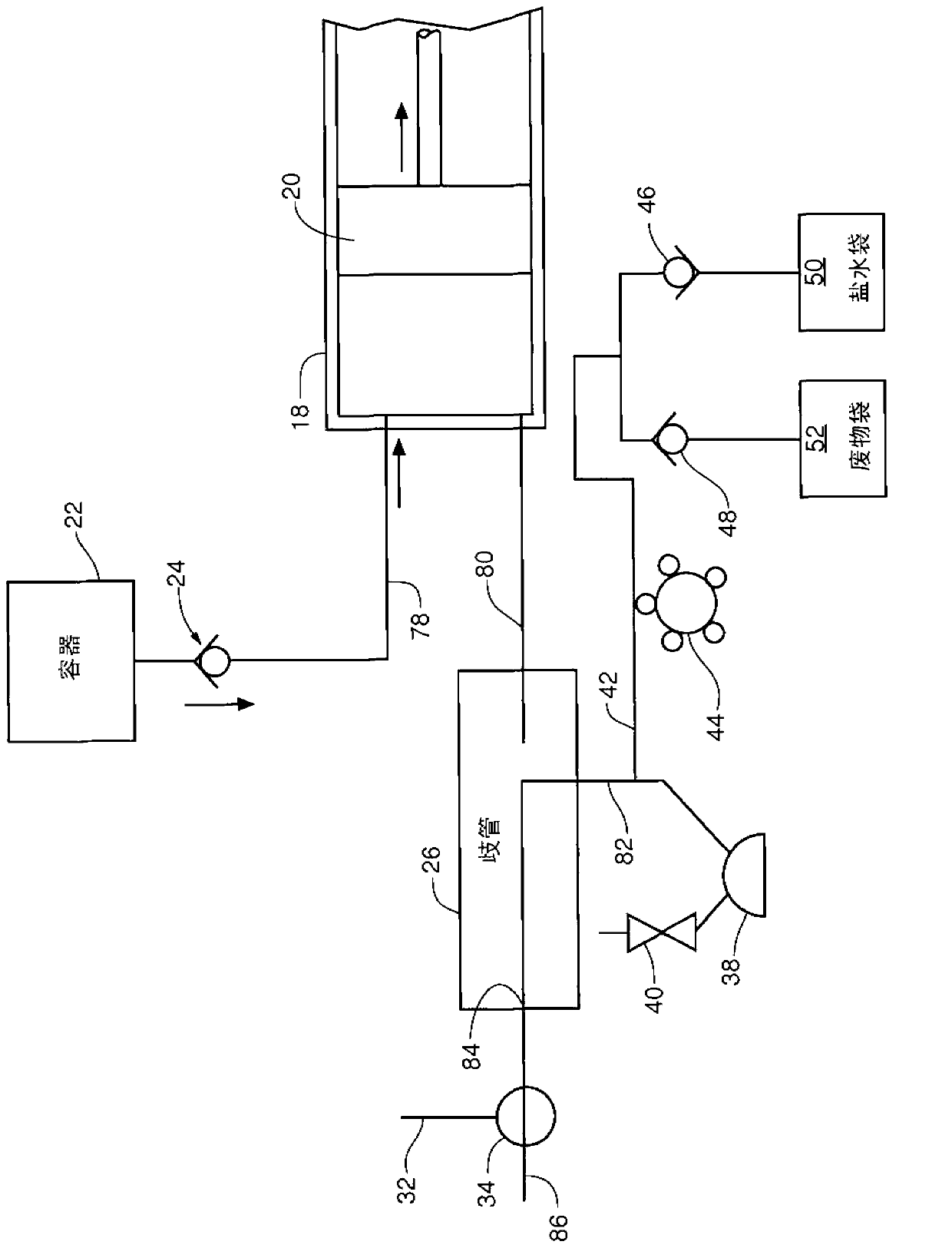
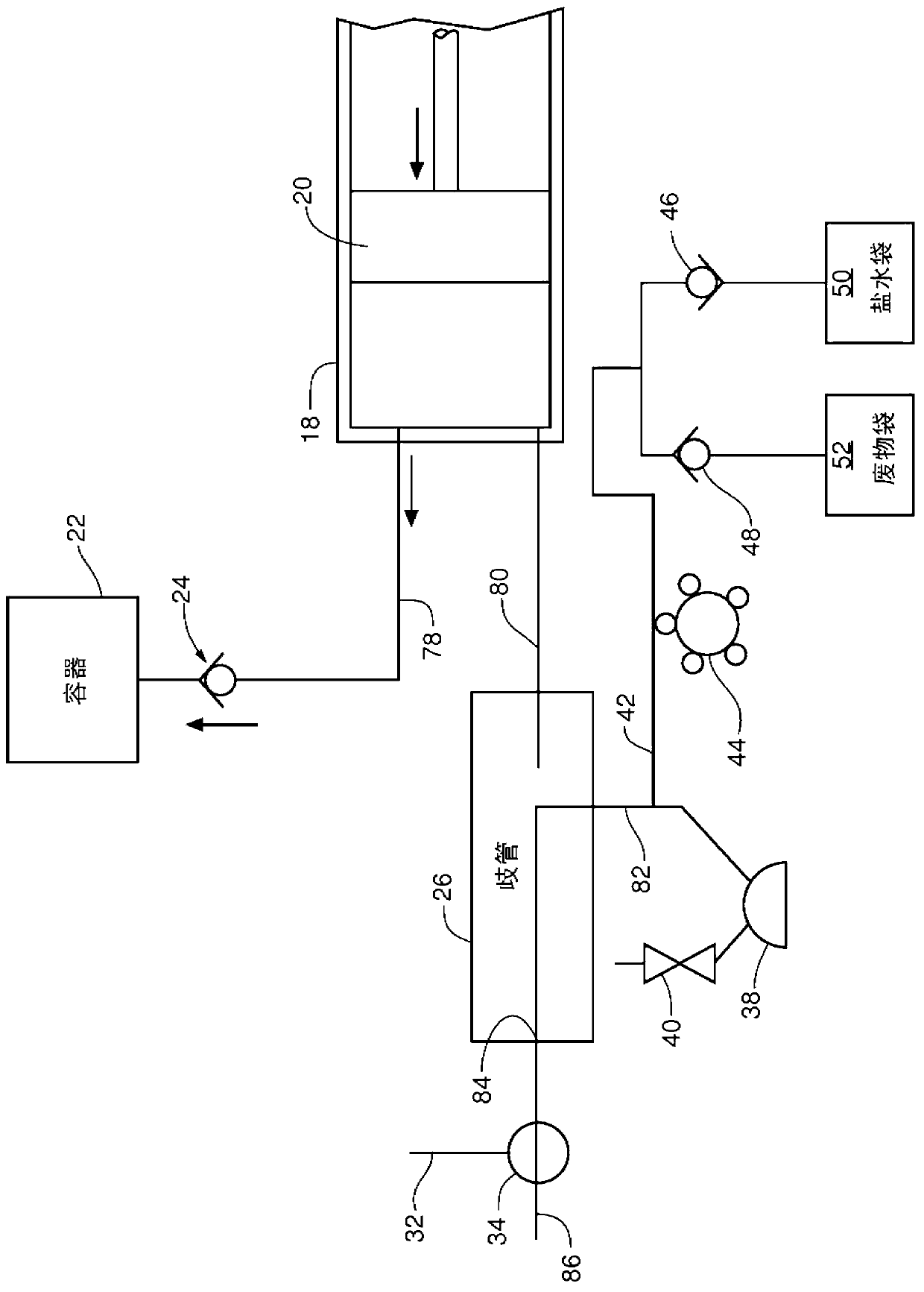
[0030] As further described below, embodiments of the present invention include syringes having an inlet valve system and syringe systems having such an inlet valve system, the syringes being able to accommodate any viscosity over a broad range of viscosities and / or at Various contrast agents of any density within a wide range of densities. This syringe and inlet valve system can be used with any contrast media injector system, including the CVi contrast media injector system offered by ACIST Medical Systems, Inc. of Eden Prairie, MN. An embodiment of a contrast media injector system and the general operation of the inlet valve system wil...


PUM


Abstract

A syringe for injecting contrast injection media into a patient. An inlet valve system associated with the syringe, the inlet valve system operable with a contrast injection media having any viscosity within the range of about 1 cP to about 30 cP. An inlet valve system associated with the syringe, the inlet valve system including a valve member having a density of less than or equal to 1 gram per cubic centimeter. A contrast injector system with such a syringe.

Description

[0001] related application [0002] This application claims the benefit of U.S. Provisional Patent Application Serial No. 61 / 416,993, filed November 24, 2010, entitled "ContrastMediaInjectorSyringeInletValveSystem," the disclosure of which is incorporated herein by reference . technical field [0003] The present application generally relates to an injector system for injecting a medical fluid, such as a contrast medium, into a living organism. Background technique [0004] Many medical procedures, such as angiography, involve injecting a contrast medium directly into the patient. Angiography is a procedure used in the diagnosis and treatment of cardiovascular disease involving abnormal or restricted blood vessels. During angiography, radiographic images of the heart or blood vessel structures are obtained by injecting a contrast agent through a catheter into a patient's veins or arteries. The injected contrast agent can be delivered to a vascular structure in fluid commu...

Claims


Application Information

Patent Timeline
Patent Type & Authority Applications(China)
IPC IPC(8): A61M39/24A61M5/00A61M5/145
CPCA61M39/24A61B6/548A61M5/007A61M5/14546A61M5/285A61M2005/287A61M2005/3106F16K15/026F16K15/06
Inventor S·D·尼斯特伦
Owner ACIST MEDICAL SYST
Why Eureka
Try Eureka