Laryngeal mask

A technology of laryngeal mask and air bag, which is applied in the field of laryngeal mask, can solve the problems of increasing patient pain, bursting, large inflation volume, etc., and achieve the effect of reducing patient pain, excellent sealing, and preventing fracture

Inactive Publication Date: 2013-09-25
CONOD MEDICAL
View PDF10 Cites 3 Cited by
  • Summary
  • Abstract
  • Description
  • Claims
  • Application Information

AI Technical Summary

Problems solved by technology

[0003] Although not limited to the two patents cited above, although each has corresponding technical effects, there are the following disadvantages: First, since the air bag inflation tube used to inflate the air bag is separated from the laryngeal mask ventilation tube, it cannot be inserted into the patient's throat. (Laryngeal cavity) operation is more troublesome; second, because the air bag inflation tube is usually relatively slender, there is a risk of rupture; , both of which are characterized by a two-pronged approach, which will increase the patient's pain, especially the risk of damage to the patient's tracheal wall; fourth, the two patents do not disclose the structure of the air bag inflation valve connected to the end of the air bag inflation tube, but in actual use In the process, not only the air bag inflation valve is required to be inflated and deflated, but also the structure is simple and the seal is reliable.
[0004] In addition, since the laryngeal mask is inserted into the patient's laryngeal cavity, it is usually impossible to observe the air bag at one end of the inflatable tube of the laryngeal mask, so there is blindness. The so-called blindness is mainly manifested in the following three aspects: First, the air bag is caused by There is leakage but there is no air, and it is in a deflated state; the second is insufficient inflation; the third is excessive inflation, and there is a risk of bursting

Method used


Image

  • Laryngeal mask
  • Laryngeal mask

Examples


Embodiment Construction

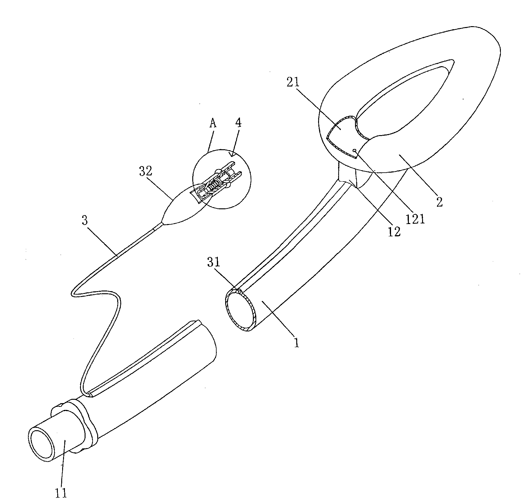
[0022] See figure 1 , provides a laryngeal mask air tube 1 that preferably uses a medical non-toxic grade polyvinyl chloride tube to serve as (responsible), and a joint 11 is formed at one end of the laryngeal mask air tube 1. The pipelines drawn from the machine are matched, and a film-type air bag 2 is combined at the other end of the laryngeal mask inflation tube 1, and an air bag inflation tube transition flange 12 is also formed at the other end of the laryngeal mask inflation tube 1. An inlet and outlet air hole 121 is provided on the transition flange 12 of the airbag inflation tube, and the inlet and outlet air hole 121 communicates with the airbag cavity 21 of the airbag 2 .

[0023] An air bag inflation tube 3 is provided, and an air bag pressure response sleeve 32 is connected to one end of the air bag inflation tube 3, and the other end of the air bag inflation tube 3 is connected to the wall of the laryngeal mask inflation tube (outer wall) of the aforementioned l...


PUM


Abstract

The invention relates to a laryngeal mask and belongs to the technical field of medical apparatus. The laryngeal mask comprises a laryngeal mask inflation tube, an air sac and an air sac inflation tube. One end of the laryngeal mask inflation tube is provided with a connector. The air sac is combined at the other end of the laryngeal mask inflation tube. An air sac inflation valve is connected to one end of the air sac inflation tube. The other end of the air sac inflation tube is connected with the air sac and communicated with an air sac cavity of the air sac. The laryngeal mask is characterized in that the other end of the air sac inflation tube is integrated with the tube wall of the laryngeal mask inflation tube. Due to the fact that the other end of the air sac inflation tube is integrated with the tube wall of the laryngeal mask inflation tube in a parasitic manner, when the laryngeal mask inflation tube is inserted into a laryngeal cavity of a patient, the air sac inflation tube is inserted jointly, convenient operation is achieved, air sac inflation tube breakage can be avoided, the patient's pain can be relieved, and damage of a trachea wall of the patient can be avoided. In addition, the air sac inflation valve is simple in structure, good in seal performance and convenient to operate.

Description

technical field [0001] The invention belongs to the technical field of medical equipment, in particular to a laryngeal mask. Background technique [0002] The function of the laryngeal mask is to maintain the breathing of an unconscious patient such as a patient who is intoxicated, and to establish a breathing channel for the patient. The technical information about the laryngeal mask can be seen in the published Chinese patent literature, typically such as the authorized announcement number CN202236740U recommending a "special laryngeal mask for bronchus", and the invention patent application publication number CN102974014A provides "built-in trachea for general anesthesia" Catheter Laryngeal Mask Combined Ventilation Device", the former of the two patent schemes is composed of a laryngeal mask ventilation tube, an air bag combined with the end of the laryngeal mask ventilation tube, and an air bag inflation tube used to inflate the air bag and connected to the air bag. An...

Claims


Application Information

Patent Timeline
Patent Type & Authority Applications(China)
IPC IPC(8): A61M16/00
Inventor 徐广
Owner CONOD MEDICAL
Why Eureka
Try Eureka