Nozzle

A nozzle and main body technology, applied in the field of nozzles for jetting fluids, can solve problems such as detrimental maintenance.

Inactive Publication Date: 2013-09-25
MISUMI
View PDF1 Cites 6 Cited by
  • Summary
  • Abstract
  • Description
  • Claims
  • Application Information

AI Technical Summary

Problems solved by technology

Therefore, if a detachment prevention part is provided to prevent detachment, maintainability is impaired.

Method used


Image

  • Nozzle
  • Nozzle
  • Nozzle

Examples


Embodiment Construction

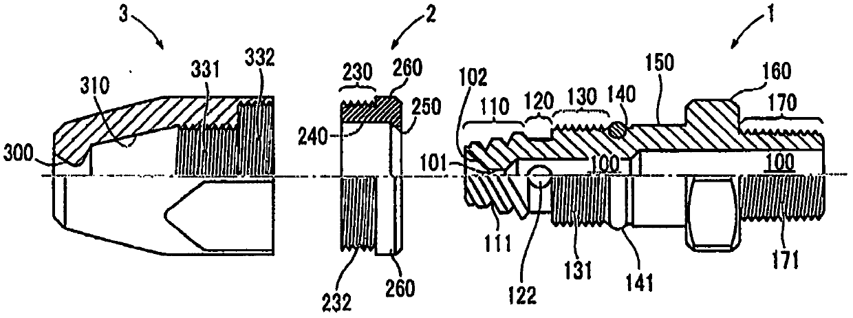
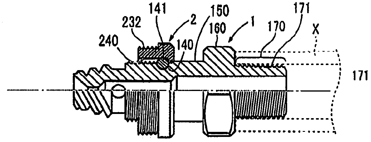
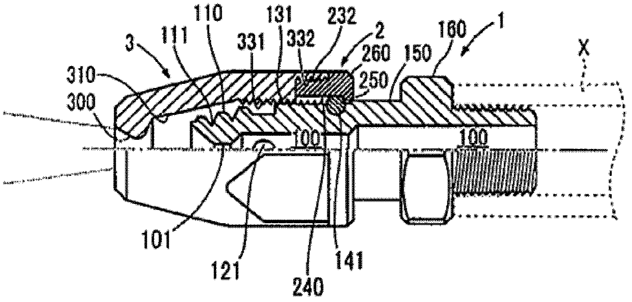
[0038] Such as figure 1 As shown, the nozzle of this embodiment is a nozzle for injecting fluid, and has a nozzle body 1 , a ring member 2 , and a nozzle cover 3 .

[0039] First, the nozzle body 1 will be described. The nozzle body 1 is a tubular member as a whole connected to a supply pipe X (see FIG. 2 ) for supplying fluid. In the present embodiment, the nozzle main body 1 is a member made of metal (made of stainless steel), but the material may be, for example, ceramics or synthetic resin.

[0040] First, there is a central pipe 100 extending along the central axis of the nozzle body 1 and communicating with the supply pipe X in the inner surface of the nozzle body 1 . Here, the inner diameter of the central pipe 100 decreases stepwise from the rear end side for connecting the supply pipe X toward the front end side and has a front end through hole 101 penetrating the front end side, and the front end of the front end through hole 101 is formed to expand in diameter. T...


PUM


Abstract

The invention provides a nozzle reliably preventing a nozzle cover from falling off and having excellent maintaining performance. The nozzle comprises a nozzle main body (1), an annular member (2) and the nozzle cover (3). The nozzle main body comprises a first conical face (110) with a conical front periphery, a helical groove (111) formed on the first conical face, a communication hole (121), a first external threaded part (131), an O ring (141), a stroke part (150) and a first flange part (160). The annular member comprises a second external threaded part (232), a second flange part (260), a sliding part (240) capable of sliding when the O ring is sealed, and a small diameter part (250). The nozzle cover comprises a nozzle hole (300), a tip-shaped second conical face (310) matching the shape of the first conical face, a first internal threaded part (331) for connecting the first external threaded part in a threaded way, and a second internal threaded part (332) for connecting with the second external threaded part in a threaded way.

Description

technical field [0001] The invention relates to a nozzle for spraying fluid. Background technique [0002] Conventionally, as this type of nozzle, a nozzle having a nozzle cover and a pipe for supplying liquid is known (refer to the following Patent Document 1, figure 1 ). The nozzle cover has two chambers of a large-diameter chamber and a small-diameter chamber inside, a nozzle hole at the front end, and a female thread portion on the inner peripheral surface on the rear end side. On the other hand, the duct has an abutment portion that abuts against the inner surface of the small-diameter chamber at the front end of the duct, a groove portion that is obliquely cut into the abutment portion, and a rear end side that is in contact with the large-diameter chamber. The plunger portion abutting against the inner surface of the chamber, the communication hole provided between the abutting portion and the plunger portion, and the external thread portion threadedly connected wit...

Claims


Application Information

Patent Timeline
Patent Type & Authority Applications(China)
IPC IPC(8): B05B1/00
Inventor 山田毅
Owner MISUMI
Why Eureka
Try Eureka