Automatic rotation part for support material
What is Al technical title?
Al technical title is built by PatSnap Al team. It summarizes the technical point description of the patent document.
A technology of automatic rotation and components, applied to other household appliances, household appliances, gears, etc., can solve the problems of low production efficiency and high labor intensity of workers
Active Publication Date: 2015-02-25
ANHUI LICHENG MACHINERY EQUIP
View PDF6 Cites 0 Cited by
Summary
Abstract
Description
Claims
Application Information
AI Technical Summary
This helps you quickly interpret patents by identifying the three key elements:
Problems solved by technology
Method used
Benefits of technology
Problems solved by technology
Automobile shaft parts need to be threaded or splined at both ends. Generally, the supporting device needs to manually change the direction of the workpiece. The labor intensity of the workers is high and the production efficiency is low.
Method used
Image
Click on the blue label to locate the original text in one second.
Reading with bidirectional positioning of images and text.
Examples
Embodiment Construction
[0011] In order to make the technical means, creative features, goals and effects achieved by the present invention easy to understand, the present invention will be further described below in conjunction with specific illustrations.
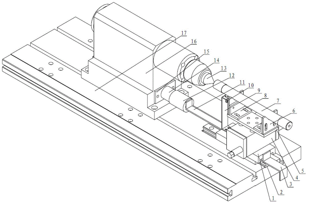
[0012] Such as figure 1 As shown, the automatic rotating support device includes a turntable saddle 1, a line rail 2, a front limit block 3, a small turntable with automatic rotation of 180° 4, a bracket bottom plate 5, a V-shaped bracket 6, and an L-shaped bracket 8 , induction switch bracket 9, induction switch 10, connecting rod 11, sleeve 12, top 13, support tube 14, front and rear baffle plates 15, top seat 16, front top slide saddle 17. The turntable saddle 1 is fixedly installed above the line rail 2, the line rail 2 is fixedly installed on the front top saddle 17, the front limit block 3 is fixedly installed on the front side of the turntable saddle 1, and the automatic rotation The 180° small turntable 4 is fixedly installed above the ...
PUM
Abstract
The invention discloses an automatic rotation part for a support material. The automatic rotation part comprises a small automatic 180-degree rotation table, a rotation table sliding saddle, a linear rail, a bracket base plate, an L-shaped bracket, a V-shaped bracket, an inductive switch support, a front limit stop block, a connection rod, a sleeve, a support cylinder, a spring, a sliding rod, a bearing, a front press cover and a rear press cover. The rotation table sliding saddle is fixed above the linear rail which is fixed on a front tailstock sliding saddle, the front limit stop block is fixed on the front side of the rotation table sliding saddle, the small automatic 180-degree rotation table is fixed above the rotation table sliding saddle, the bracket base plate is fixed on the small automatic 180-degree rotation table 4, the L-shaped bracket is fixed on the bracket base plate, the V-shaped bracket is fixed on the L-shaped bracket, the inductive switch support is mounted on the rotation table sliding saddle, an inductive switch is mounted on the inductive switch support, the connection rod is fixed between the rotation table sliding saddle and an internal sliding guide rod of the sleeve, a tailstock is mounted on a tailstock base, front and rear baffles are mounted on the tailstock base to prevent the bearing from being exposed, and the tailstock base is mounted on the front tailstock sliding saddle. By means of the automatic rotation part, automation is achieved, and a basis is provided for continuous production.
Description
technical field [0001] The invention relates to the technical field of gear rubbing machines, in particular to an automatic rotating part for supporting materials. Background technique [0002] The gear rubbing machine is widely used in the processing of various involute splines, involute saw teeth, threads, oil grooves, screws and knurls. It can process high-precision workpieces within a few seconds within its processing capacity. Automobile shaft parts need to be threaded or splined at both ends of the workpiece. Generally, the supporting device needs to manually change the direction of the workpiece. The labor intensity of the workers is high and the production efficiency is low. Contents of the invention [0003] The present invention provides a solution to the above-mentioned problems, and proposes an automatic rotating component for supporting materials. [0004] The technical problem to be solved by the present invention is to realize the automatic rotation of the ...
Claims
Application Information
Patent Timeline
Application Date:The date an application was filed.
Publication Date:The date a patent or application was officially published.
First Publication Date:The earliest publication date of a patent with the same application number.
Issue Date:Publication date of the patent grant document.
PCT Entry Date:The Entry date of PCT National Phase.
Estimated Expiry Date:The statutory expiry date of a patent right according to the Patent Law, and it is the longest term of protection that the patent right can achieve without the termination of the patent right due to other reasons(Term extension factor has been taken into account ).
Invalid Date:Actual expiry date is based on effective date or publication date of legal transaction data of invalid patent.