Sand sprayer for locomotives and application method thereof

A technology of sand spreader and locomotive, which is applied in the field of sand spreader, which can solve the problem of high sand standard requirements, achieve the effects of reducing particle size requirements, inhibiting locomotive idling, and smooth sand production

Active Publication Date: 2013-09-25
湖南联诚电气科技有限公司
View PDF8 Cites 6 Cited by
  • Summary
  • Abstract
  • Description
  • Claims
  • Application Information

AI Technical Summary

Problems solved by technology

[0003] In order to overcome the problem that existing sand spreaders have high requirements for sand standards, the purpose of the present invention is to provide a sand spreader for locomotives

Method used


Image

  • Sand sprayer for locomotives and application method thereof
  • Sand sprayer for locomotives and application method thereof
  • Sand sprayer for locomotives and application method thereof

Examples


Embodiment Construction

[0026] In order to make the technical problems, technical solutions and beneficial effects solved by the present invention clearer, the following further describes the present invention in detail with reference to the accompanying drawings and embodiments. It should be understood that the specific embodiments described herein are only used to explain the present invention, but not to limit the present invention.

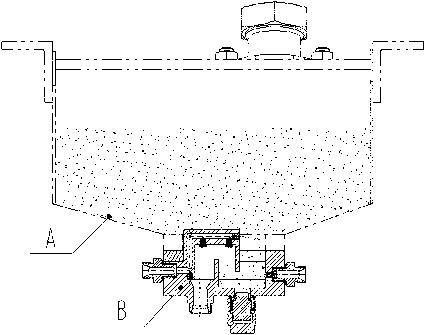
[0027] The invention provides a sand remover for locomotives, which is installed at the lower part of the sand box A. The sand box A may be various sand boxes in the prior art. Such as figure 1 Shown:

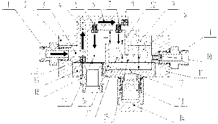
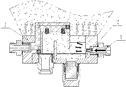
[0028] The structure of the sand spreader B is as follows Figure 1-5 As shown, it includes a sand-spreading body provided with a chamber 9 and a high-pressure air duct communicating with the chamber 9. An upright partition 16 separates the chamber 9 from the bottom of the chamber 9 into an upper communicating chamber 15 and a sand outlet. Chamber 17, the sand inlet cha...


PUM

PropertyMeasurementUnit
particle sizeaaaaaaaaaa

Abstract

A sand sprayer for locomotives is installed below a sandbox and comprises a sand spray body provided with a cavity and a high-pressure air flue which communicates with the cavity. A vertical separator plate divides the cavity from the bottom into a sand inlet cavity and a sand outlet cavity, wherein the upper parts of both the sand inlet cavity and the sand outlet cavity communicate with each other. The sand inlet cavity is divided by a suspended cavity wall of the sand inlet cavity from the upper part into a sand inlet chamber and a sand lift chamber, wherein bottoms of both the sand inlet chamber and the sand lift chamber communicate with each other. The sand inlet chamber communicates with a sandbox outlet. The top of the sand lift chamber is provided with a sand lift tuyere which communicates with the high-pressure air flue. The sand lift tuyere blows sand, which flows into the sand inlet chamber from the sandbox and enters the sand lift chamber through the bottom of the sand inlet chamber, into the sand outlet cavity. The top of the sand outlet cavity is provided with a sand outlet tuyere which communicates with the high-pressure air flue and is used for blowing sand out of a sand outlet at the bottom of the sand outlet cavity. The invention also provides an application method of the sand sprayer. The sand sprayer provided by the invention is applicable to be used under the condition of nonuniform particle size of sand grains and is not easy to obstruct. By the use of the sand sprayer, sand flow is smooth, idle running of locomotives can be inhibited timely, and normal operation of locomotives is guaranteed.

Description

Technical field [0001] The invention relates to a component for an electric locomotive, in particular to a sand spreader and a method of use thereof. Background technique [0002] During the operation of electric locomotives, due to rain, snow, freezing, and oil pollution, the adhesion coefficient between the wheels and the track becomes small, which will cause problems such as wheel idling and sliding. The solution is to install a sand spreader on the electric locomotive to spread sand , That is, continue to sprinkle dry sand between the wheel tread and the wheel rail. In the process of sand removal, it is necessary to control the sand from the sand box to continuously flow into the sand spreader, replenish the sand in the sand spreader chamber, and blow the sand out of the chamber evenly and spread it between the wheel tread and the wheel rail. In the state of high-speed operation of electric locomotives, the movement of sand particles is affected by various factors. Therefore...

Claims


Application Information

Patent Timeline
Patent Type & Authority Applications(China)
IPC IPC(8): B61C15/10
Inventor 段绪连侯知青王晟晟
Owner 湖南联诚电气科技有限公司
Why Eureka
Try Eureka