
Mechanical arm paw for robot palletizer and manufacturing method of mechanical arm paw

A palletizing robot and mechanical gripper technology, applied in the field of packaging and transfer equipment, can solve the problems of increasing labor costs, inability to grasp, and the weight of the gripper is heavy, and achieves high transfer and palletizing efficiency, wide application range, and high versatility. Effect

Active Publication Date: 2013-09-25
JIANGSU ZHONGKE YOUTE ROBOT TECH
View PDF7 Cites 48 Cited by
  • Summary
  • Abstract
  • Description
  • Claims
  • Application Information

AI Technical Summary

Problems solved by technology

However, most of the existing mechanical grippers are rigid grasping grippers, which are easy to damage the grasped objects, and most of the grippers can only grab one product at a time, and the weight of the grippers that can grab multiple products at the same time is also relatively heavy, which reduces the reliability. grab weight
[0003] In addition, the clamping position of the traditional grabbing claw is limited, only the side or bottom surface can be clamped, and it must be multi-sided.
When the object to be grasped is an irregular box, it cannot be grasped
At the same time, the palletizing trays for stacking the objects to be grabbed are placed manually, which increases the labor cost and reduces the efficiency of transshipment and palletizing; and when the objects to be grabbed are soft materials, the traditional mechanical claws cannot grasp them.
[0004] Obviously, the existing mechanical grippers cannot meet the requirements of high-speed transfer, and the grasping range is limited and the grasped objects are easily damaged, so the reliability is poor

Method used


Image

  • Mechanical arm paw for robot palletizer and manufacturing method of mechanical arm paw
  • Mechanical arm paw for robot palletizer and manufacturing method of mechanical arm paw

Examples


Embodiment Construction

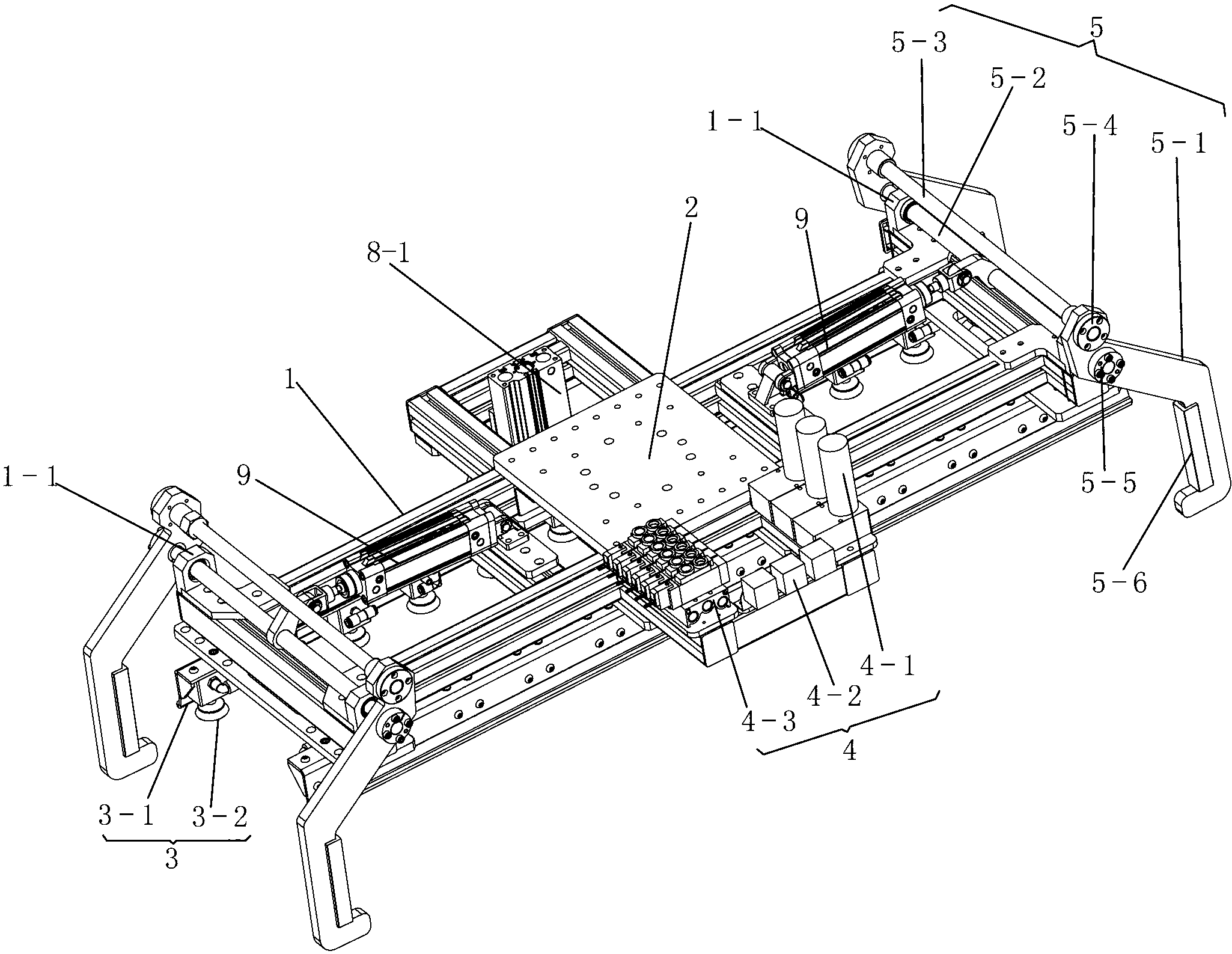
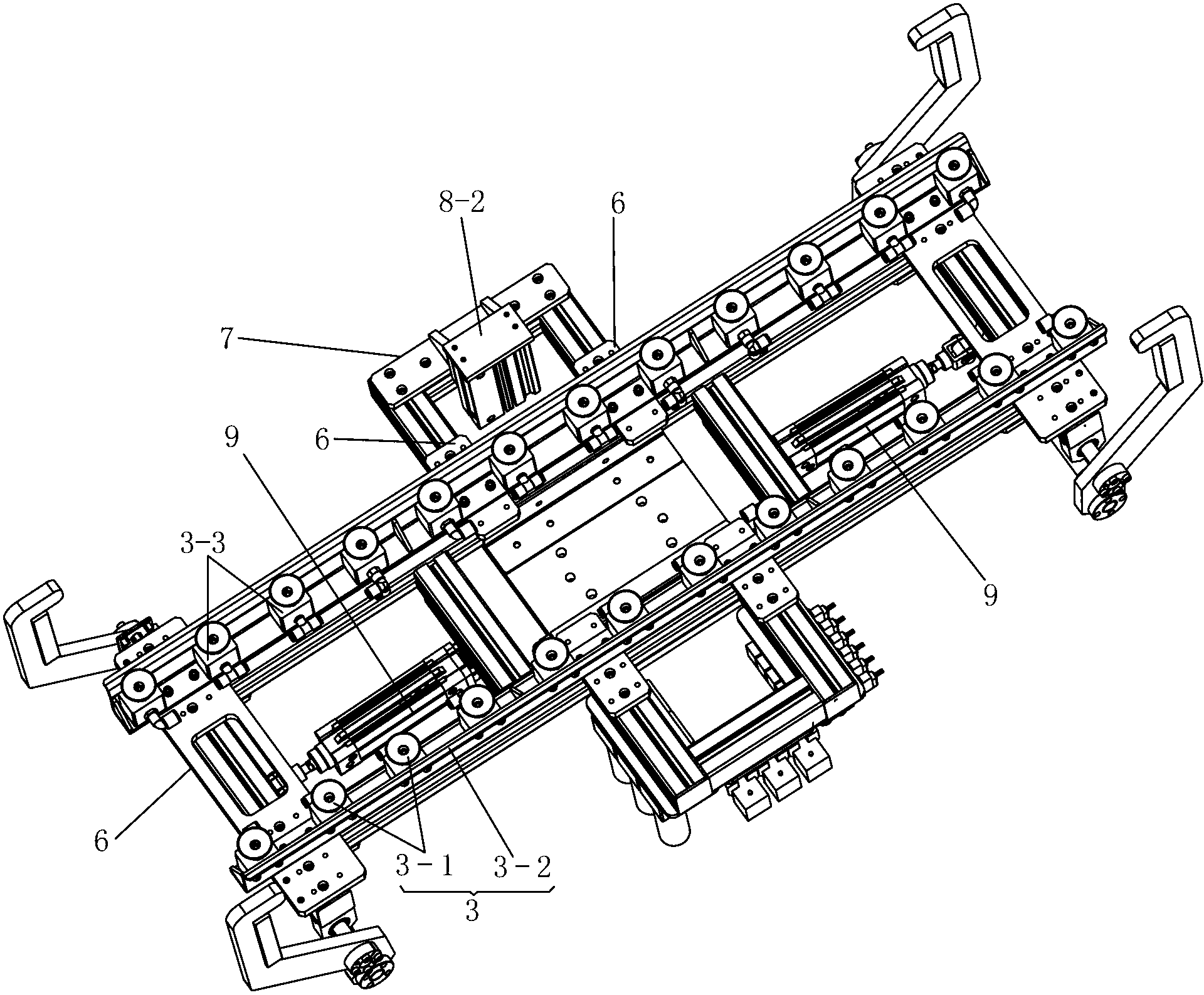
[0027] See Figure 1-2 , the manipulator claw for palletizing robot of the present invention, comprises: the connection flange 2 that links to each other with the mechanical arm of palletizing robot, the installation frame 1 that links to each other with this connection flange 2 bottom surfaces, this installation frame 1 is rectangular, is located at installation The brackets on both sides of the middle part of the frame 1 are connected to the suction cup device 3 on the installation frame 1 through a plurality of mounting plates 6, the vacuum control device 4 on one bracket, and the height detection device on the other bracket 7 , the grasping device 5 installed symmetrically at both ends of the installation frame 1 , and the cylinder drive device 9 provided on the installation frame 1 .

[0028] The suction cup device 3 includes: a pair of suction cup connecting baffles 3-1 arranged on both side edges of the installation frame 1, ten to twenty suction cup mounting seats 3 ev...


PUM


Abstract

The invention relates to a mechanical arm paw for a robot palletizer. The mechanical arm paw comprises a connecting flange, an installing frame, supports, a sucker device, a vacuumizing control device, a height detecting device, grabbing devices and an air cylinder driving device. The connecting flange is connected with a mechanical arm of the robot palletizer, the installing frame which is in a rectangular shape is connected with the bottom surface of the connecting flange, the supports are arranged on the two sides of the middle of the installing frame, the sucker device is connected to the installing frame through a plurality of installing plates, the vacuumizing control device is arranged on one support, the height detecting device is arranged on the other support, the grabbing devices are symmetrically installed at the two ends of the installing frame, and the air cylinder driving device is installed on the installing frame. Compared with the prior art, the mechanical arm paw has the advantages of being strong in universality, high in transporting and stacking efficiency and the like, and grabbed objects cannot be damaged.

Description

technical field [0001] The invention relates to the technical field of packaging and transshipment equipment, in particular to a mechanical claw for a palletizing robot, specifically, it can automatically grab and place palletizing pallets, absorb and release the packaging through a vacuum corrugated suction cup, and cooperate with the palletizing robot. A palletizing robot manipulator claw device that uses a mechanical arm to realize the transfer and palletizing functions of packages of different sizes. Background technique [0002] In recent years, as the production automation of enterprises has become higher and higher, the application of palletizing robots has become more and more common, and the supporting claws of palletizing robots have also developed rapidly. However, most of the existing mechanical grippers are rigid grasping grippers, which are easy to damage the grasped objects, and most of the grippers can only grab one product at a time, and the weight of the gr...

Claims


Application Information

Patent Timeline
Patent Type & Authority Applications(China)
IPC IPC(8): B65G61/00
Inventor 张识超苗登雨赵贤相邹阳冯宝林莫贤徐林森孙玉萍
Owner JIANGSU ZHONGKE YOUTE ROBOT TECH
Learn More