
Planetary cone-ring transmission

A technology for planetary cone rings and transmissions, which is applied to gear transmissions, belts/chains/gears, mechanical equipment, etc. It can solve the problems that are difficult to satisfy the power and economy of the whole vehicle at the same time, and achieve a large range of transmission ratio coverage. The effect of light weight and small size

Inactive Publication Date: 2013-09-25
李青山
View PDF1 Cites 7 Cited by
  • Summary
  • Abstract
  • Description
  • Claims
  • Application Information

AI Technical Summary

Problems solved by technology

A simple single planetary row can meet the requirements of positive and negative output rotation, but it is difficult to meet the requirements of vehicle power and economy at the same time

Method used


Image

  • Planetary cone-ring transmission
  • Planetary cone-ring transmission
  • Planetary cone-ring transmission

Examples


Embodiment Construction

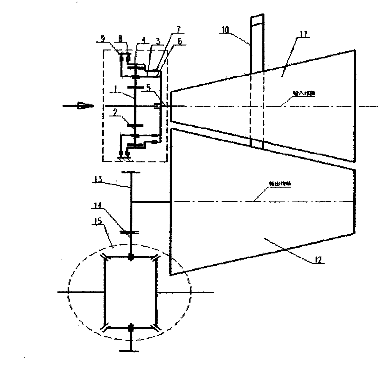
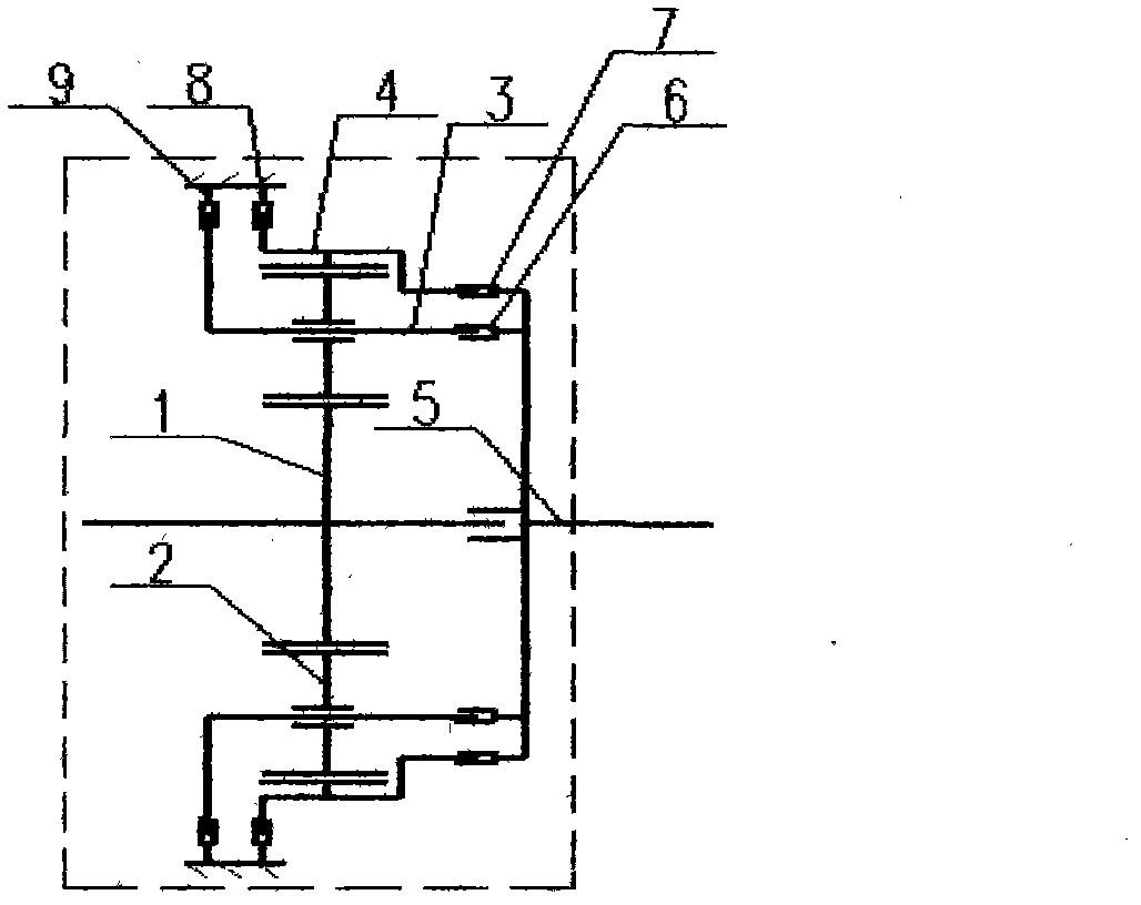
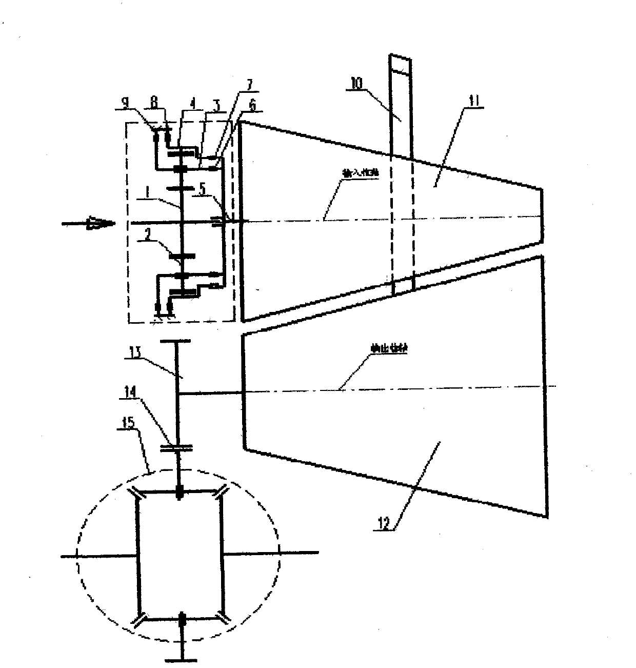
[0017] In the figure, the schematic diagram of the three-speed single-row planetary gear transmission is shown in the square virtual frame, the schematic diagram of the differential is shown in the circular virtual frame, the schematic diagram of the cone-ring continuously variable transmission is composed of the driving cone 11, the ring 10 and the driven cone 12, and the main reducer It consists of main deceleration small teeth 13 and main deceleration large teeth 14.

[0018] Figure 1-5 The working principle of the three-speed single-row planetary gear transmission shown in is: the power is input from the sun gear 1 and output from the output shaft 5. By manipulating four clutches 6, 7, 8, 9, each gear is realized. Neutral: All 4 clutches are disengaged. Forward low gear: clutches 6 and 8 are engaged, and clutches 7 and 9 are disengaged. Forward high gear: clutches 6 and 7 are engaged, clutches 8 and 9 are disengaged, and the speed ratio is 1:1. Reverse gear: Clutches ...


PUM


Abstract

The invention provides a planetary cone-ring transmission, which is characterized by in-line arrangement of a three-gear single-row planetary gear transmission device and a cone-ring continuous variable transmission device and is provided with two forward gears and a reverse gear. When a vehicle runs at low speed and requires higher driving performance, a forward low speed gear of the three-gear single-row planetary gear transmission device is matched with the cone-ring continuous variable transmission device for use; when the vehicle runs at high speed and requires higher traveling performance, a forward high speed gear of the three-gear single-row planetary gear transmission device is matched with the cone-ring continuous variable transmission device for use; when the vehicle is backed, the reverse gear of the three-gear single-row planetary gear transmission device is matched with the cone-ring continuous variable transmission device for use. Therefore, the transmission can meet the requirement of the vehicle better.

Description

technical field [0001] The invention relates to a transmission, especially suitable for a planetary cone-ring transmission in which a three-speed single-row planetary gear transmission and a cone-ring continuously variable transmission are arranged in line for a vehicle. Background technique [0002] U.S. Patent No. 1,709,346 describes a cone-ring continuously variable transmission device in which the parallel shafts are mutually inverted and the cones are used to transmit power and shift speed through the cone-to-cone ring. In order to realize the positive and negative output rotation and compact structure of the device, a simple single planetary row is often used in conjunction with it. With the development of modern industry, some fields put forward higher requirements on the volume, weight and coverage of the gear ratio of the transmission. For example, some vehicles require the transmission device to be small in size, light in weight, and have a large range of transmis...

Claims


Application Information

Patent Timeline
Patent Type & Authority Applications(China)
IPC IPC(8): F16H3/76
Inventor 李青山
Owner 李青山
Learn More