Distance measuring and speed measuring methods and devices based on video images

A technology of video image and ranging method, applied in the field of speed measurement and ranging, can solve the problems of low real-time measurement and low measurement accuracy, improve real-time performance and accuracy, simplify the process of video ranging, and avoid internal and external parameters of the camera. The effect of the calibration process

Inactive Publication Date: 2013-09-25
CHENGDU UNIVERSITY OF TECHNOLOGY
View PDF4 Cites 16 Cited by
  • Summary
  • Abstract
  • Description
  • Claims
  • Application Information

AI Technical Summary

Problems solved by technology

It can overcome the problems of low measurement accuracy and low real-time measurement in the existing technology

Method used


Image

  • Distance measuring and speed measuring methods and devices based on video images
  • Distance measuring and speed measuring methods and devices based on video images
  • Distance measuring and speed measuring methods and devices based on video images

Examples


Embodiment Construction

[0040] Before introducing the distance measuring and speed measuring methods of the embodiments of the present invention, the principles of the embodiments of the present invention will be described first. Before explaining the principle, it is necessary to introduce the geometric relationship of camera imaging.

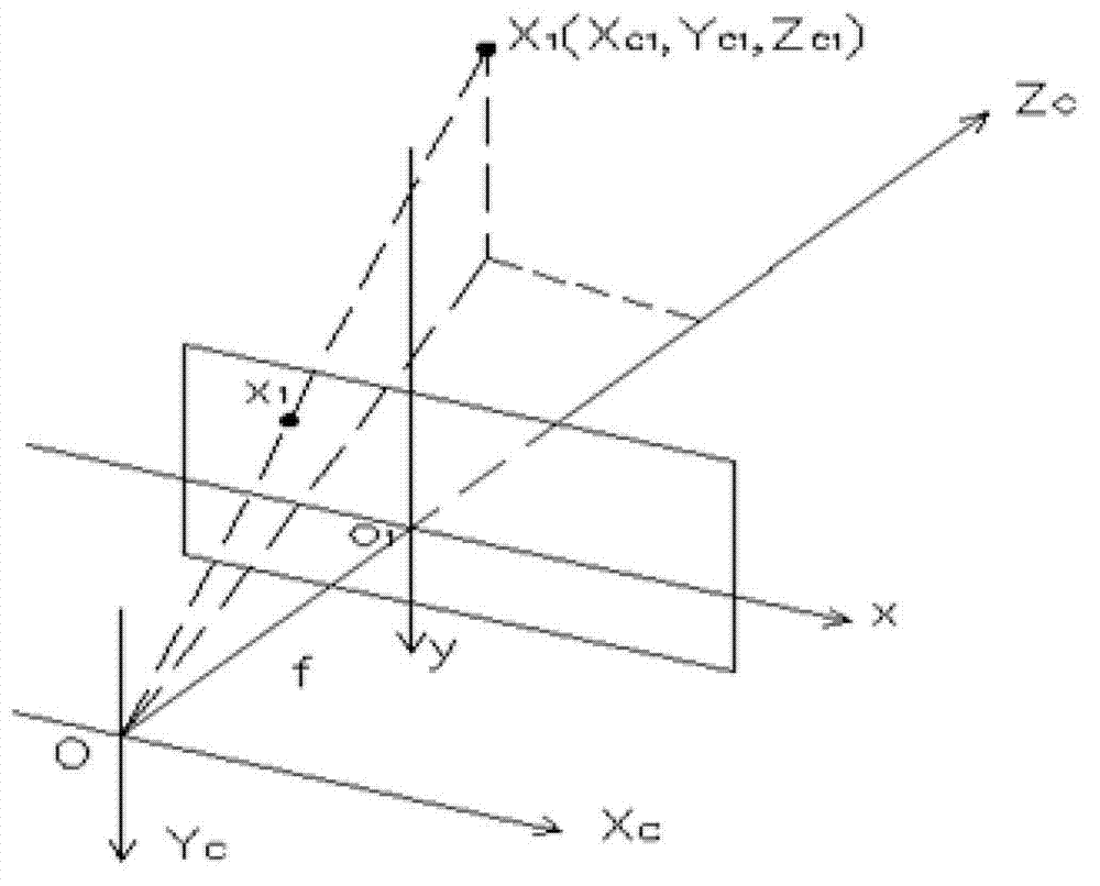
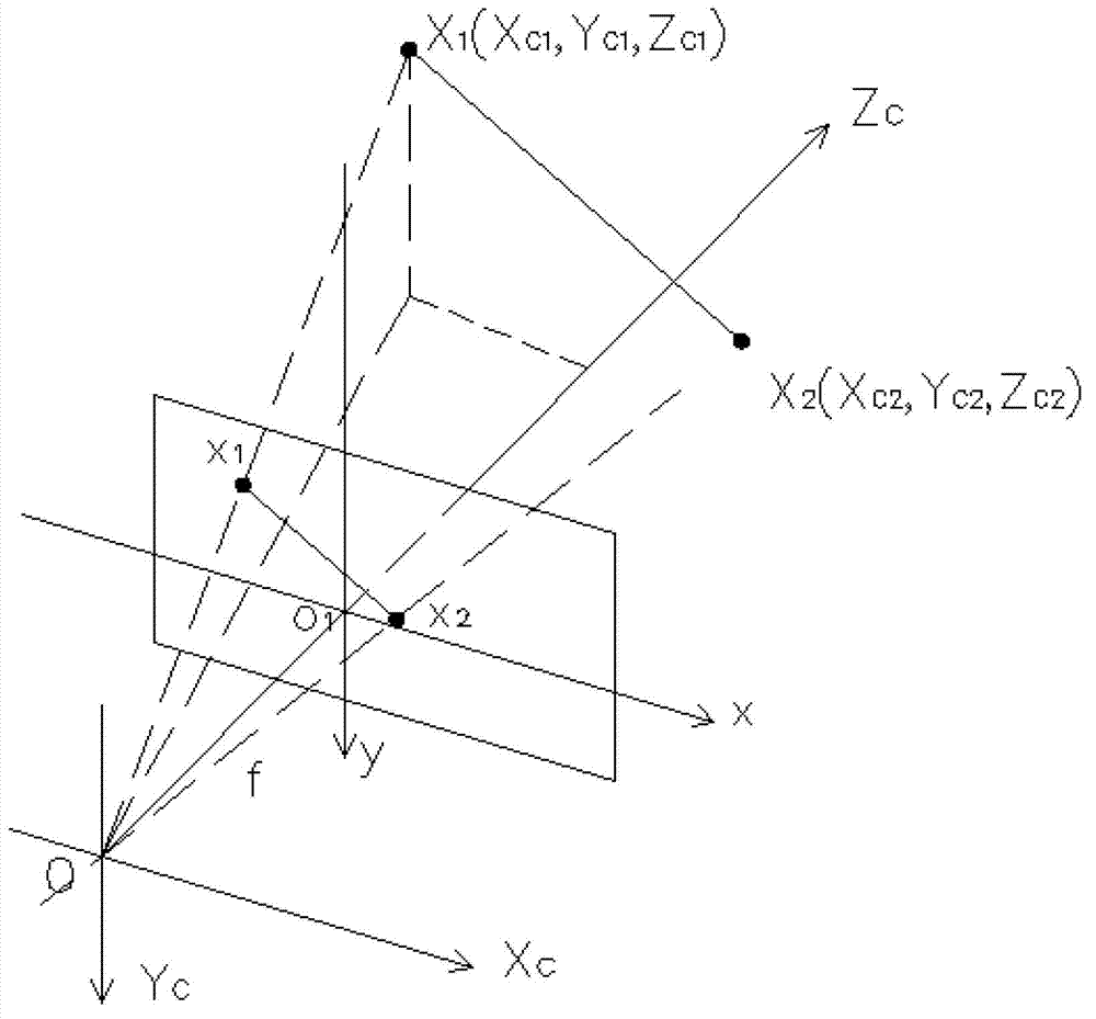
[0041] Such as figure 1 Shown is the geometric relationship diagram of camera imaging. In the illustration, point 0 is the optical center of the camera, O-X C Y C Z C is the camera coordinate system, the optical axis Z of the camera C The intersection point with the image plane is O 1 , with O 1 Establish the image coordinate system O for the coordinate origin 1 -xyz c , where the x-axis of the image coordinate system and the X-axis of the camera coordinate system C The axes are parallel, the y-axis of the image coordinate system and the Y-axis of the camera coordinate system C The axes are parallel, the z axis of the image coordinate system and the Z of th...


PUM


Abstract

The invention provides distance measuring and speed measuring methods and devices based on video images. On the premise that a movement track of a measured object is perpendicular to a camera optical axis and the movement track of the measured object is a straight line, when the measured object moves from point A to point B in the movement track, distance between point A' and point B' is measured, wherein the point A' and point B' are corresponding points of the point A and the point B in an image plane. The distance between the point A and the point B is measured, according to the measured distance between the point A' and the point B' and a mapping proportionality coefficient of the distance in the movement track to the corresponding distance in the image plane. By adopting of the methods and the devices, real-time performance and accuracy of the measurement can be improved.

Description

technical field [0001] The present invention relates to distance measurement and speed measurement technology, in particular to a method and device for distance measurement and speed measurement based on video images. Background technique [0002] At present, the distance measurement and speed measurement methods based on video images mainly rely on the camera imaging model. The points in the world coordinate system are determined by establishing the mapping equation between the midpoint of the image coordinate system and the midpoint of the world coordinate system, and then the point in the world coordinate system is calculated. Distance, the speed of the object is determined according to the distance and time in the world coordinate system. This method is universal, but because the measurement process involves the calibration of the internal and external parameters of the camera, the process is not only complicated and computationally intensive, it is difficult to meet the...

Claims


Application Information

Patent Timeline
Patent Type & Authority Applications(China)
IPC IPC(8): G01C11/36G01C3/00G01P3/68
Inventor 刘明哲庹先国刘小于王磊李怀良成毅杨剑波
Owner CHENGDU UNIVERSITY OF TECHNOLOGY
Why Eureka
Try Eureka