Nondestructive plate testing method with Lamb wave mode control based on electromagnetic ultrasonic receiving transducer

An electromagnetic ultrasonic and non-destructive testing technology, applied in the use of sound waves/ultrasonic waves/infrasonic waves for material analysis, using sound waves/ultrasonic waves/infrasonic waves to analyze solids, instruments, etc. The effect of weakening the influence of the Lamb wave multi-mode

Inactive Publication Date: 2013-09-25
HARBIN INST OF TECH
View PDF1 Cites 6 Cited by
  • Summary
  • Abstract
  • Description
  • Claims
  • Application Information

AI Technical Summary

Problems solved by technology

[0003] In order to solve the problem that the echo signal is complicated due to the multi-mode characteristics of the electromagnetic ultrasonic Lamb wave, and the nondestructive testing of the plate cannot be realized, the present invention proposes a plate nondestructive testing method based on the Lamb wave mode control of the electromagnetic ultrasonic receiving transducer

Method used


Image

  • Nondestructive plate testing method with Lamb wave mode control based on electromagnetic ultrasonic receiving transducer
  • Nondestructive plate testing method with Lamb wave mode control based on electromagnetic ultrasonic receiving transducer
  • Nondestructive plate testing method with Lamb wave mode control based on electromagnetic ultrasonic receiving transducer

Examples


specific Embodiment approach 1

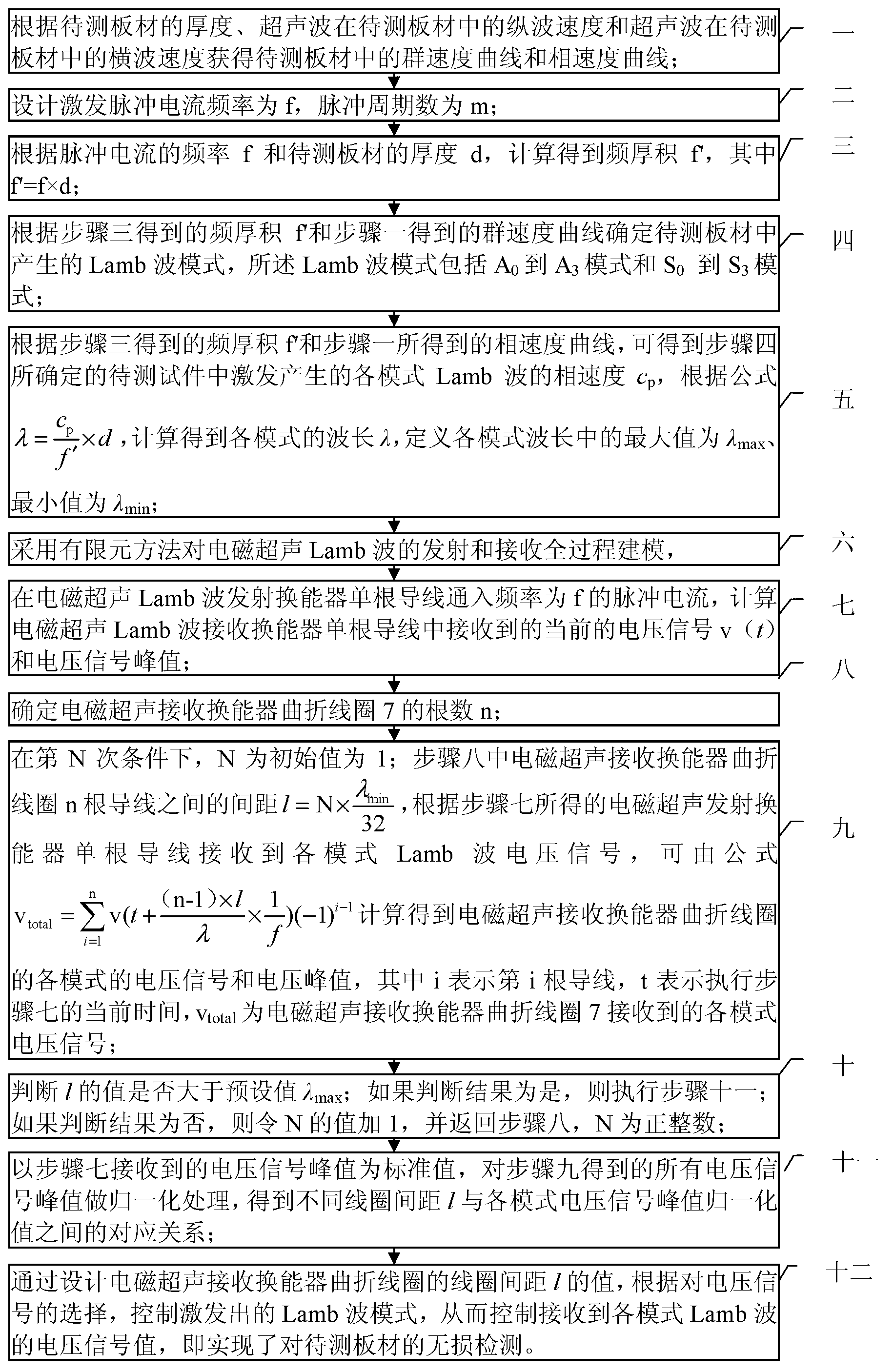
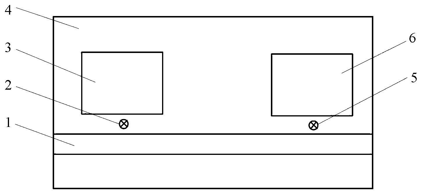
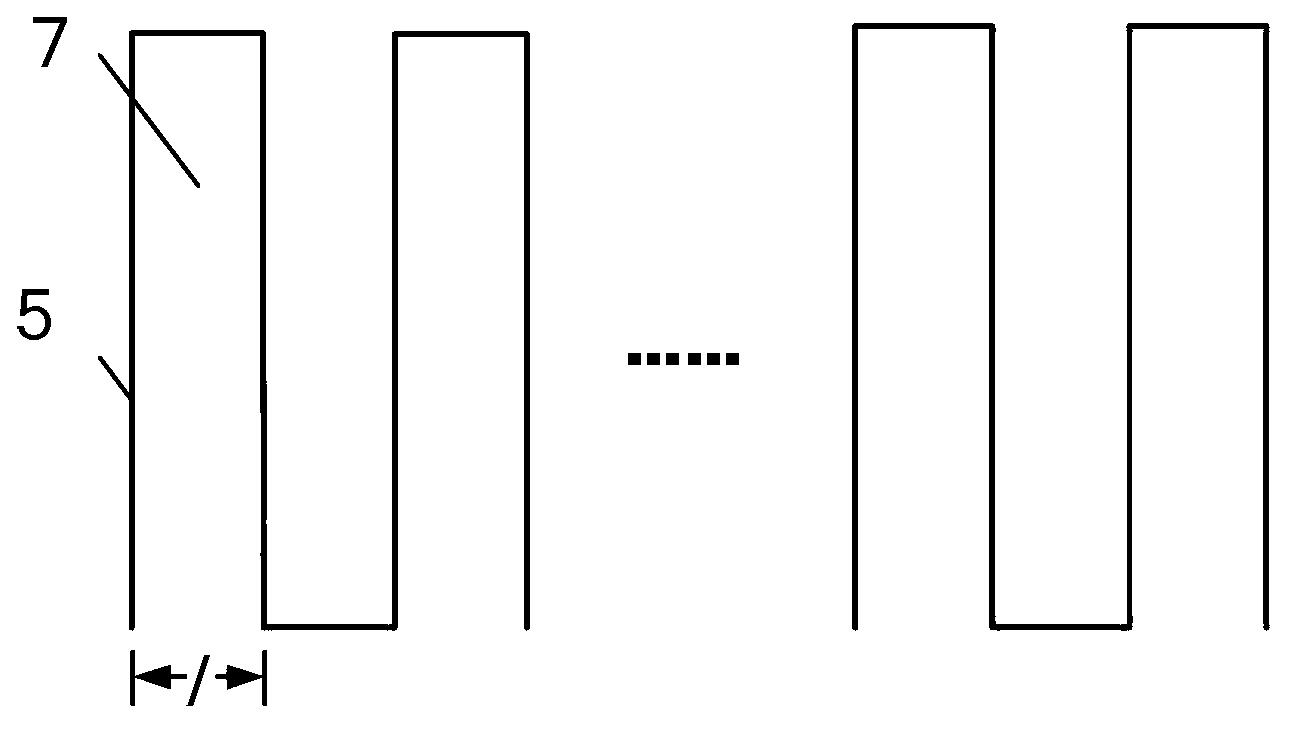
[0030] Specific implementation mode one: combine figure 1 , figure 2 and image 3 Describe this embodiment mode, a kind of plate material non-destructive testing method based on the Lamb wave mode control of the electromagnetic ultrasonic receiving transducer described in this embodiment mode, it is realized by the following steps:

[0031] Step 1: Obtain the group velocity curve and the phase velocity curve in the plate to be tested according to the thickness of the plate to be tested, the longitudinal wave velocity of the ultrasonic wave in the plate to be tested, and the transverse wave velocity of the ultrasonic wave in the plate to be tested;

[0032] Step 2: Design the excitation pulse current frequency as f and the number of pulse cycles as m;

[0033] Step 3: Calculate the frequency-thickness product f′ according to the frequency f of the pulse current and the thickness d of the plate to be measured, where f′=f×d;

[0034] Step 4: Determine the Lamb wave mode gener...

specific Embodiment approach 2

[0048] Specific embodiment 2: This embodiment is a further limitation of the plate non-destructive testing method based on the Lamb wave mode control of the electromagnetic ultrasonic receiving transducer described in the specific embodiment 1: when the plate to be tested in the step 1 Aluminum alloy plate with a thickness of 2mm.

specific Embodiment approach 3

[0049] Specific embodiment 3: This embodiment is a further limitation of the plate non-destructive testing method based on the Lamb wave mode control of the electromagnetic ultrasonic receiving transducer described in the specific embodiment 1: the frequency f of the pulse current in the step 7 500kHz.


PUM

PropertyMeasurementUnit
thicknessaaaaaaaaaa

Abstract

The invention discloses a nondestructive plate testing method with Lamb wave mode control based on an electromagnetic ultrasonic receiving transducer, which belongs to the technical field of converter control. The Lamb wave mode control method based on the electromagnetic ultrasonic receiving transducer aims to solve the problem that an echo signal is complex and cannot be detected due to the multi-mode characteristics of electromagnetic ultrasonic Lamb waves. The method comprises the following steps of: determining an excitation wave mode in a plate according to excitation parameters, modeling and solving the total process of transmitting and receiving electromagnetic ultrasonic Lamb waves by a finite element method, and analyzing a corresponding relationship between the coil distance l of rectangular-wave-shaped winding coils of the electromagnetic ultrasonic Lamb wave transducer and a voltage signal in each mode, wherein the voltage signal amplitude of the received Lamb wave in each mode can be controlled through the set value l, namely the aim of controlling the electromagnetic ultrasonic Lamb wave mode is fulfilled. The method is widely applied to control on the Lamb wave mode by the electromagnetic ultrasonic method.

Description

technical field [0001] The invention belongs to the technical field of converter control. technical background [0002] At present, the non-contact ultrasonic non-destructive testing can be realized by using the electromagnetic ultrasonic testing method. The Lamb wave has small attenuation along the propagation path, a large detection range, and high sensitivity. one of the ways. The use of electromagnetic ultrasonic transducers can easily excite and generate Lamb waves in the board. Unlike other types of ultrasonic waves, Lamb waves have multi-mode characteristics, which will have a negative impact on ultrasonic testing. If multiple modes of Lamb waves propagate in the plate at the same time, the received time-domain signal has multiple envelopes, and different modes will encounter defects or boundary mode conversion, resulting in the received signal is very complex and difficult to detect. resolution, resulting in detection failure. Regarding the adverse effects of mult...

Claims


Application Information

Patent Timeline
Patent Type & Authority Applications(China)
IPC IPC(8): G01N29/07G01N29/32
Inventor 翟国富宫佳鹏蒋韬刘博李智超王亚坤李鹏展
Owner HARBIN INST OF TECH
Why Eureka
Try Eureka