Novel current transformer saturation identification method

A technology of current transformers and identification methods, which is applied in the direction of instruments, measuring electricity, and measuring electrical variables, etc. It can solve problems such as difficulty in setting the saturation point flux linkage value, difficulty in accurate measurement of time difference, long data window of harmonic method, etc.

Inactive Publication Date: 2013-09-25
XI AN JIAOTONG UNIV
View PDF3 Cites 16 Cited by
  • Summary
  • Abstract
  • Description
  • Claims
  • Application Information

AI Technical Summary

Problems solved by technology

These methods mainly use the current waveform characteristics when the current transformer is saturated, but there are the following defects: the time difference method is easily affected by the system operation mode and the initial phase angle of the fault when applied, so it is difficult to accurately measure the time difference; The method requires a long data window, and the action speed of the protection will be limited. In addition, this method is disturbed by the fault current harmonics of the system, and the threshold value of the criterion is not easy to set; the secondary load and current transformer excitation required by the magnetic braking method It is difficult to adjust the flux linkage value at the saturation point of the curve

Method used

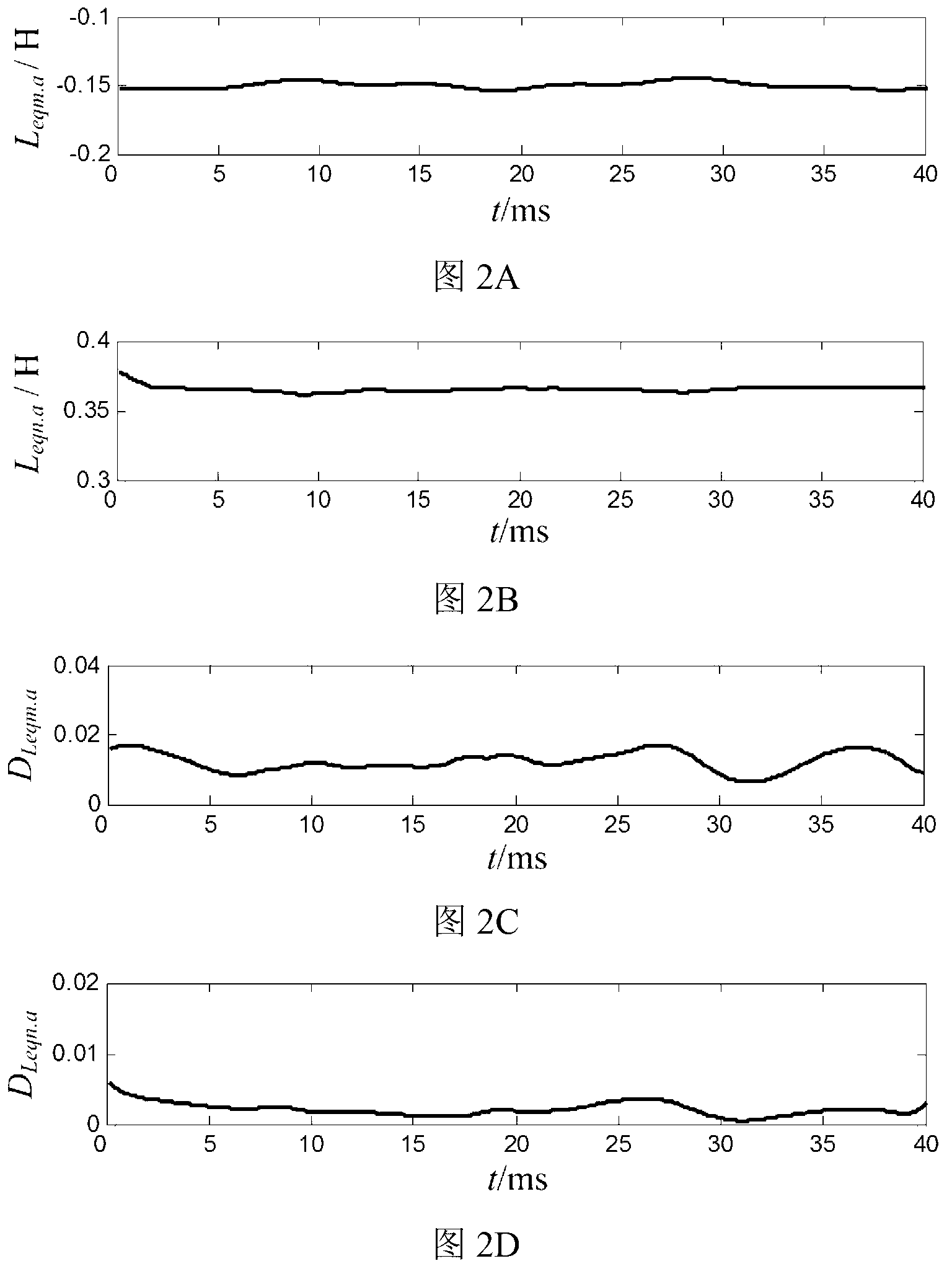
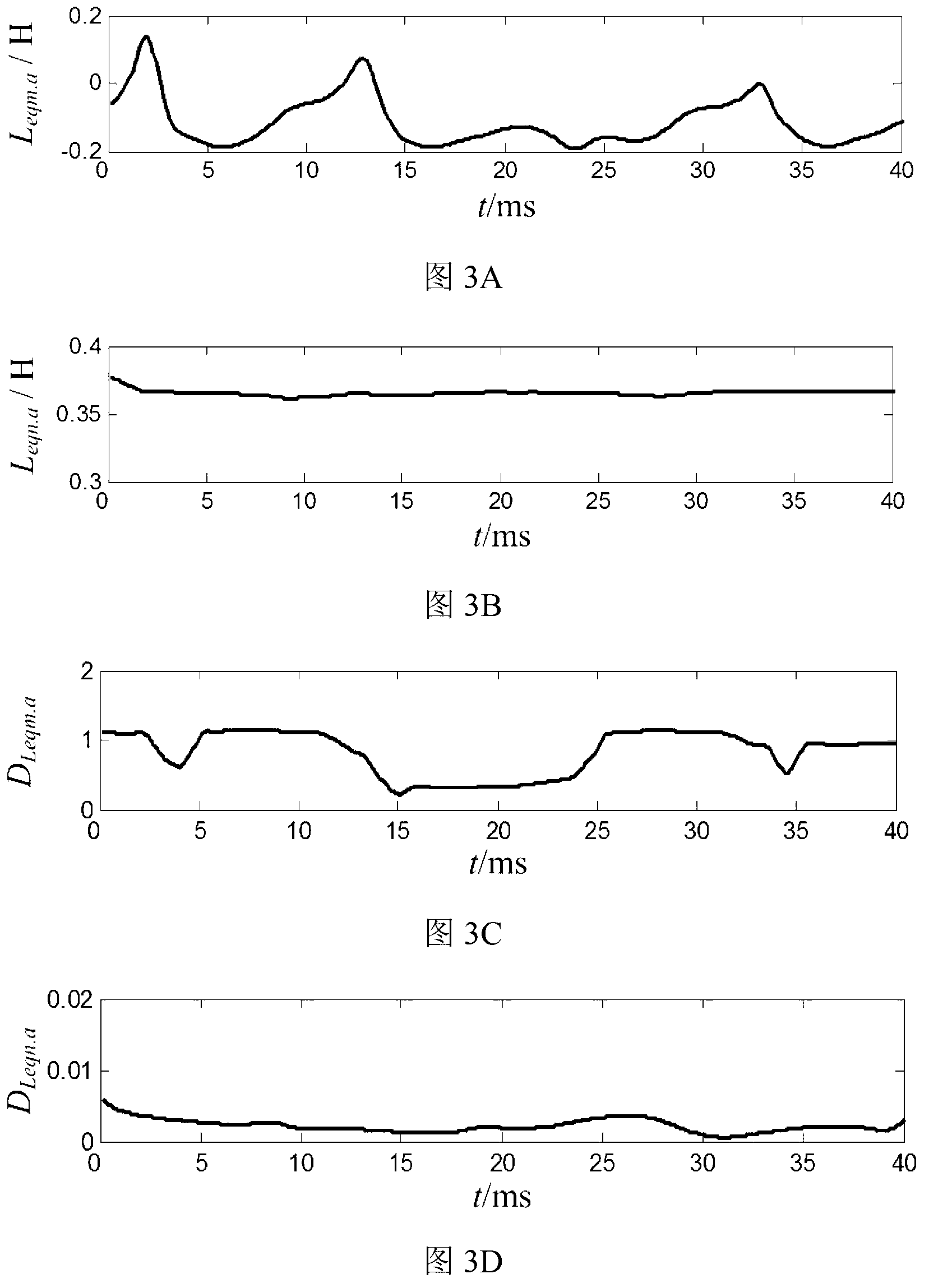

Image

  • Novel current transformer saturation identification method
  • Novel current transformer saturation identification method
  • Novel current transformer saturation identification method

Examples


Embodiment Construction

[0039] The application of the present invention to line protection will be further described in detail below in conjunction with the accompanying drawings.

[0040] In this embodiment, a novel current transformer saturation identification method is applied to but not limited to a 200km long 500kV transmission line, and specifically includes the following steps:

[0041] Step 1. The protective devices at both ends of the line (m-terminal and n-terminal) respectively collect the instantaneous value data of the three-phase voltage and current at the protective installation of the local end, and the sampling frequency is set to 5kHz. At this time, the number of sampling points per power frequency cycle is N=100 , sampling time interval T s =0.2ms; record the sampling result as u ma (k), u mb (k), u mc (k), i ma (k), i mb (k), i mc (k), u na (k), u nb (k), u nc (k), i na (k), i nb (k), i nc (k);

[0042] Step 2. Calculate the three-phase voltage and current fault compo...


PUM


Abstract

Disclosed is a novel current transformer saturation identification method. The novel current transformer saturation identification method includes the steps that 1, three-phase voltage and electric current instantaneous value data at protective installation positions of current transformers are collected, and sampling results are recorded as ua(k), ub(k), uc(k), ia(k), ib(k) and ic(k); 2, the three-phase voltage and electric current fault component are calculated, namely, delta ua(k), delta ub(k), delta uc(k), delta ia(k), delta ib(k) and delta ic(k); 3, equivalent inductance and resistance parameters are calculated, namely, L(eq.j) and R(eq.j) (j=a, b ,c); 4, dispersion of the resistance parameters is calculated (j=a, b ,c); 5, whether all phases of mutual inductors are saturated is judged and recognized, if D(L(eq.a)) > epsilon, then the a-phase mutual inductor is judged to be saturated, if D(L(eq.b)) > epsilon, then the b-phase mutual inductor is judged to be saturated, and if D(L(eq.c)) > epsilon, then the c-phase mutual inductor is judged to be saturated. The novel current transformer saturation identification method is simple and reliable, and is not affected by system operation modes and fault initial phase angles because only short data windows are used.

Description

technical field [0001] The invention relates to the technical field of electric power system relay protection, in particular to a novel current transformer saturation identification method. Background technique [0002] In the power system, the transformer is the contact element between the primary system and the secondary system, which is used to monitor and control the normal operation and fault conditions of electrical equipment. The correct transmission and transformation of the primary side signal by the protective transformer is the premise of the correct action of the relay protection, and it is also the key to improve the protection performance. [0003] The current transformer saturation problem affects the differential protection of power system components such as lines, transformers, and buses, and is a public problem that plagues relay protection workers. For this reason, scholars at home and abroad have proposed a variety of current transformer saturation ident...

Claims


Application Information

Patent Timeline
Patent Type & Authority Applications(China)
IPC IPC(8): G01R31/00
Inventor 康小宁姚旭焦在滨宋国兵马超
Owner XI AN JIAOTONG UNIV
Why Eureka
Try Eureka