Control method and control system executing same

A control method and control system technology, applied in two-dimensional position/channel control and other directions, can solve problems such as inability to slot, easily change the position of the boundary line, and damage the integrity of the grass.

Inactive Publication Date: 2013-09-25
POSITEC POWER TOOLS (SUZHOU) CO LTD
View PDF7 Cites 31 Cited by
  • Summary
  • Abstract
  • Description
  • Claims
  • Application Information

AI Technical Summary

Problems solved by technology

The disadvantage of this method is that the embedding of the boundary line requires professional tools to make grooves on the grass, which is time-consuming and laborious, and will destroy the integrity of the grass
In addition, for some specific robots, it is impossible to slot in their work area, such as indoor vacuum cleaners, which are not suitable for slotting and laying boundary lines on the ground in the city
However, if the boundary line is laid directly on the ground surface of the work area, the position of the boundary line is easy to change, making the work area in a state of change, which cannot meet the needs of users
[0005] In order to solve the deficiencies in the prior art of setting the working area by laying boundary lines, it is necessary to develop a control method and control system that can conveniently and reliably control the automatic walking equipment to work in the preset virtual working area

Method used


Image

  • Control method and control system executing same
  • Control method and control system executing same
  • Control method and control system executing same

Examples


Embodiment Construction

[0092] The detailed description and technical content of the present invention are described below with accompanying drawings, but the attached drawings are only for reference and description, and are not intended to limit the present invention.

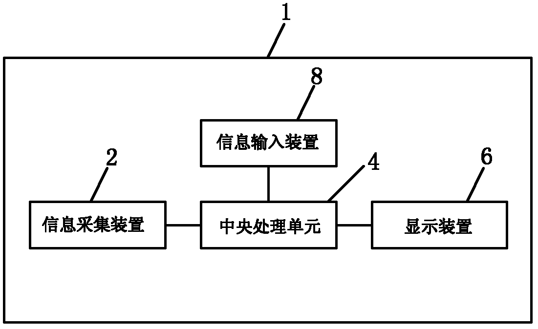
[0093] Such as figure 1 As shown, the boundary setting system 1 includes an information collection device 2, a central processing unit 4, a display device 6, and an information input device 8, wherein the information collection device 2, the display device 6, and the information input device 8 are all electrically connected to the central processing unit 4. connect. The information collection device 2 collects images of the monitoring area and transmits them to the central processing unit 4 . The central processing unit 4 receives the image transmitted by the information collection device 2 and generates a global image covering the monitoring area. The display device 6 displays the global image according to the control of the centr...


PUM


Abstract

The invention relates to a control system and a control method. An automatic walking device can be controlled to work on the basis of a preset working area. The control method includes the following steps that a positioning device outputs position information of the automatic walking device to a central processing unit, the central processing unit determines a position, corresponding to the working area, of the automatic walking device according to the position information, a corresponding control signal is produced on the basis of the position, corresponding to the working area, of the automatic walking device, and the automatic walking device adjusts a working mode according to the control signal. According to the control system and the control method, on the basis of a virtual working area which is preset in the central processing unit, when the automatic walking device is controlled to work in a practical environment, working is conducted in a practical working area which is matched with the virtual working area, therefore, a user does not need to pave a border line by hand to plan the practical working area of the automatic walking device, and work for planning the working area of the automatic walking device by the user is greatly simplified.

Description

technical field [0001] The invention relates to a control method, in particular to a control method for controlling automatic walking equipment to work in a preset virtual working area. [0002] The invention relates to a control system, in particular to a control system for controlling automatic walking equipment to work in a preset virtual working area. Background technique [0003] With the development of science and technology, intelligent automatic walking equipment is well known to people. Since the automatic walking equipment can automatically perform pre-set related tasks without human operation and intervention, it is widely used in industrial applications and household products. The application is very extensive. Industrial applications such as robots that perform various functions, and applications in household products such as lawn mowers and vacuum cleaners, these intelligent automatic walking equipment greatly save people's time and bring great benefits to ind...

Claims


Application Information

Patent Timeline
Patent Type & Authority Applications(China)
IPC IPC(8): G05D1/02
Inventor 强尼·鲍瑞那图
Owner POSITEC POWER TOOLS (SUZHOU) CO LTD
Why Eureka
Try Eureka