A pixel circuit, a display device and a driving method of the pixel circuit

A pixel circuit and capacitor technology, which is applied in the field of display devices and pixel circuits, can solve the problems of threshold voltage drift, uneven image display, uneven organic light-emitting diode current, etc., and achieve the effect of reducing production costs and uniform brightness display

Active Publication Date: 2016-02-03
BOE TECH GRP CO LTD +1
View PDF4 Cites 0 Cited by
  • Summary
  • Abstract
  • Description
  • Claims
  • Application Information

AI Technical Summary

Problems solved by technology

[0003] In view of this, the present invention provides a pixel circuit, a display device, and a driving method for the pixel circuit, which are used to solve the problem that the currents flowing through different organic light-emitting diodes are different when receiving the same data voltage due to the threshold voltage drift of the existing driving transistors. Uniformity, which causes the problem of uneven display of the entire image

Method used


Image

  • A pixel circuit, a display device and a driving method of the pixel circuit
  • A pixel circuit, a display device and a driving method of the pixel circuit
  • A pixel circuit, a display device and a driving method of the pixel circuit

Examples


Embodiment 1

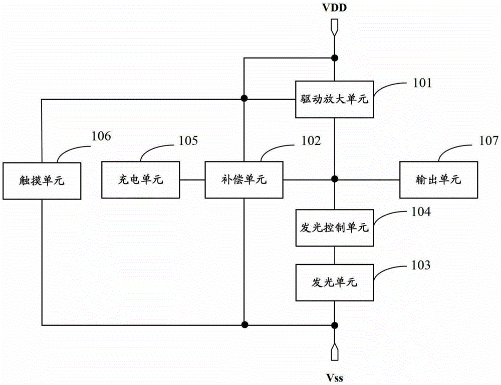
[0028] Please refer to figure 1 , figure 1 It is a schematic diagram of the connection structure of the pixel circuit according to Embodiment 1 of the present invention. The pixel circuit includes: a driving amplification unit 101, a compensation unit 102, a light emitting unit 103, a light emitting control unit 104, a charging unit 105, a touch unit 106 and an output unit 107;

[0029] The light-emitting unit 103 is connected to the light-emitting control unit 104 and the low-voltage terminal Vss respectively, and is used to perform light-emitting display under the control of the light-emitting control unit 104; the light-emitting unit 103 can be an organic light-emitting diode (OLED) (OrganicLight- EmittingDiode);

[0030] The light-emitting control unit 104 is connected to the light-emitting unit 103 and the driving amplifier unit 101 respectively, and is used to control the light-emitting unit 103 to emit light and display in the display stage;

[0031] The touch unit 10...

Embodiment 2

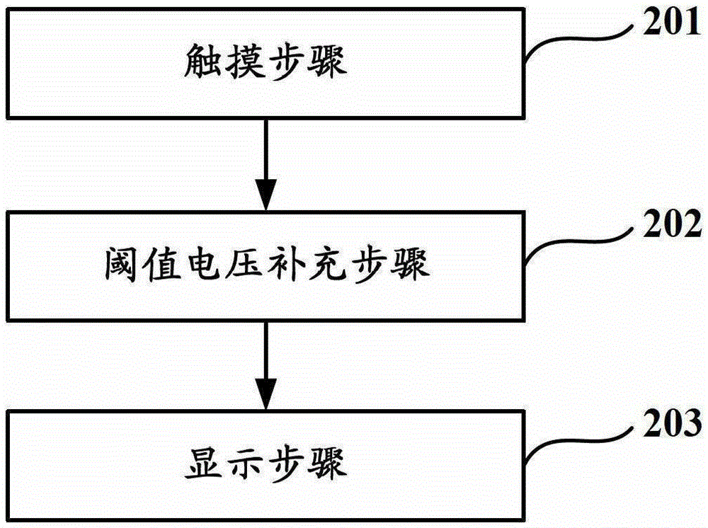
[0042] Corresponding to the pixel circuit in the first embodiment, the second embodiment of the present invention also provides a driving method for the pixel circuit, refer to figure 2 , figure 2 It is a schematic flowchart of a driving method for a pixel circuit according to Embodiment 2 of the present invention, and the method includes the following steps:

[0043] Touching step 201: the touch unit 106 generates a touch signal, the driving amplifying unit 101 amplifies the touch signal, and the output unit 107 outputs the touch signal amplified by the driving amplifying unit 101;

[0044] Threshold voltage compensation step 202: the high voltage terminal VDD charges the compensation unit 102, so that the gate voltage of the driving amplifying unit 101 is equal to the threshold voltage of the driving amplifying unit 101;

[0045] Displaying step 203: the charging unit 105 charges the compensation unit 102 so that the gate voltage of the driving amplifier unit 101 is equal...

Embodiment 3

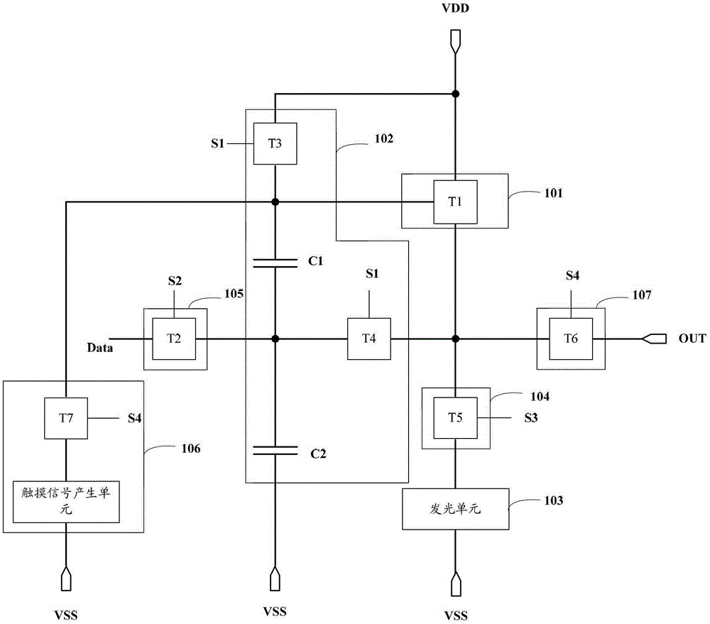
[0048] Please refer to image 3 , image 3 It is a schematic diagram of the connection structure of the pixel circuit according to the third embodiment of the present invention. The pixel circuit includes: a driving amplification unit 101, a compensation unit 102, a light emitting unit 103, a light emitting control unit 104, a charging unit 105, a touch unit 106 and an output unit 107;

[0049] The light-emitting unit 103 is configured to perform light-emitting display under the control of the light-emitting control unit 104;

[0050] The light-emitting control unit 104 is configured to control the light-emitting unit 103 to display light during the display stage;

[0051] The touch unit 106 is configured to generate a touch signal;

[0052] The drive amplification unit 101 is used to amplify the touch signal generated by the touch unit 106 during the touch phase, and drive the light emitting unit 103 to emit light and display during the display phase;

[0053] The output u...


PUM


Abstract

The present invention is directed to a pixel circuit for a display device and to a method for driving the pixel circuit. The pixel circuit comprises: a light-emitting unit configured to emit light under the control of the light-emission controlling unit; a light-emission controlling unit configured to control the light-emitting unit to emit light at a display stage; a touching unit configured to generate a touch signal; a driver amplifying unit configured to amplify the touch signal at a touch stage and drive the light-emitting unit to emit light at the display stage; a charging unit configured to charge a compensating unit; the compensating unit configured to be charged by the high voltage end prior to the display stage, and be charged by the charging unit at the display stage.

Description

technical field [0001] The present invention relates to the field of display technology, in particular to a pixel circuit, a display device and a driving method for the pixel circuit. Background technique [0002] Active Matrix Organic Light Emitting Diode (AMOLED) displays have been widely used due to their advantages of wide viewing angle, good color contrast effect, fast response speed and low cost. Active matrix organic light-emitting diodes can emit light by driving a thin film transistor (ThinFilmTransistor, TFT) when the current generated in a saturated state is driven. The thin film transistor backplane will have non-uniformity and stability problems during the process, which will cause the threshold voltage (Vth) of the driving thin film transistor to drift. Since the driving current for lighting up the active matrix organic light emitting diode is related to the threshold voltage of the driving thin film transistor, when the threshold voltage of the driving thin f...

Claims


Application Information

Patent Timeline
Patent Type & Authority Patents(China)
IPC IPC(8): G09G3/3233G06F3/041
CPCG06F3/04166G09G3/3233G09G2300/0852G09G2300/0861G09G2354/00G09G2360/148G06F3/0412G09G3/3258G09G2300/0819G09G2320/0233G09G2320/045
Inventor 吴博祁小敬
Owner BOE TECH GRP CO LTD
Why Eureka
Try Eureka