Arc-control device and arc-control method of direct-current mechanical switch
A technology of mechanical switch and arc extinguishing device, which is applied in electrical switches, electrical components, circuits, etc., can solve the problems of large size, inconvenient promotion and popularization of professional DC switches, and high price.
- Summary
- Abstract
- Description
- Claims
- Application Information
AI Technical Summary
Problems solved by technology
Method used
Image
Examples
Embodiment 1
[0035] Embodiment 1: The DC mechanical switch is installed on the positive line side of the DC power supply line
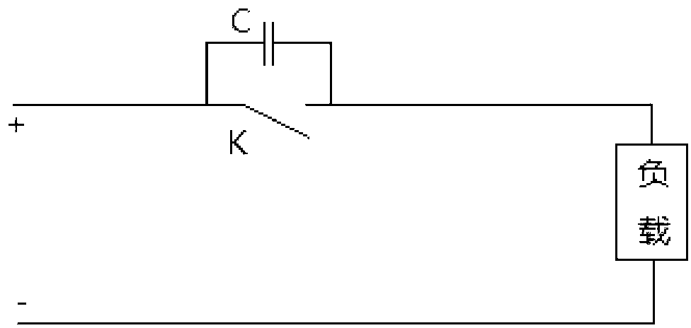
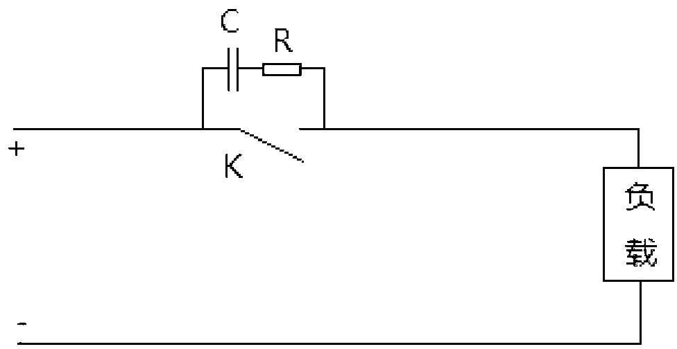
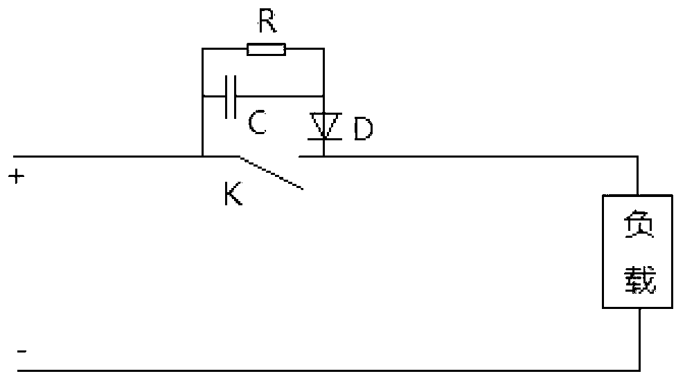
[0036] When the DC mechanical switch is installed on the positive line side of the DC power supply line, the absorption circuit can be flexibly set. In this embodiment, four types of snubber circuits are listed.
[0037] The first absorption circuit:
[0038] like figure 1 As shown, the snubber circuit is capacitor C.
[0039] Its working principle is:
[0040] S1, when the DC mechanical switch K is in the closed state, the capacitor C is in a short-circuit state, and the DC current is output to the load after passing through the DC mechanical switch;
[0041] S2, when the DC mechanical switch K changes from the closed state to the open state, that is, during the process of the moving contact of the DC mechanical switch K gradually moving away from the static contact, the capacitor C changes from the short circuit state to the conduction state, and the DC mech...
Embodiment 2
[0053] Embodiment 2: The DC mechanical switch is installed on the negative line side of the DC power supply line
[0054] When the DC mechanical switch is installed on the negative line side of the DC power supply line, the snubber circuit can be flexibly set. In this embodiment, four types of snubber circuits are listed.
[0055] like Figure 5 As shown, the snubber circuit is capacitor C.
[0056] like Image 6 As shown, the absorbing circuit is a series RC circuit.
[0057] like Figure 7 and Figure 8 As shown, the absorption circuit is an RCD circuit; wherein, the RCD circuit includes a resistor R, a capacitor C and a diode D; the diode D is connected in series with the capacitor C, and the resistor R and the capacitor C are connected in parallel. specific, Figure 7 Among them, the current output end of the diode D is electrically connected to the input end of the resistor R and the capacitor C connected in parallel; Figure 8 Among them, after the resistor R and...
Embodiment 3
[0059] Embodiment 3: DC mechanical switches are respectively installed on the positive line side and the negative line side of the DC power supply line
[0060] Specifically, such as Figure 9 As shown, the DC mechanical switch includes a first DC mechanical switch and a second DC mechanical switch; the first DC mechanical switch is installed on the positive line side of the DC power supply line, and the second DC mechanical switch is installed on the negative line side of the DC power supply line .
[0061] A first absorption circuit is connected in parallel at both ends of the first DC mechanical switch, and a second absorption circuit is connected in parallel at both ends of the second DC mechanical switch. Among them, the structure of the first snubber circuit is the same as Figure 1 to Figure 4 The structure of the same, the structure of the second snubber circuit and Figure 5 to Figure 8 have the same structure and will not be described in detail here.
[0062] In ...
PUM
 Abstract
Description
Claims
Application Information
 - R&D Engineer
- R&D Manager
- IP Professional
- Industry Leading Data Capabilities
- Powerful AI technology
- Patent DNA Extraction
Browse by: Latest US Patents, China's latest patents, Technical Efficacy Thesaurus, Application Domain, Technology Topic, Popular Technical Reports.
© 2024 PatSnap. All rights reserved.Legal|Privacy policy|Modern Slavery Act Transparency Statement|Sitemap|About US| Contact US: help@patsnap.com


