
Heat radiating structure of outdoor type inverter cabinet body and outdoor type inverter cabinet body

A technology of inverter cabinet and heat dissipation structure, which is applied in the direction of irreversible DC power input conversion to AC power output, cooling/ventilation/heating transformation, casing/cabinet/drawer parts, etc., which can solve the problem of air volume reduction , Increase the pollution level of the working environment of the inverter, reduce the heat dissipation effect of the inverter, etc., to achieve the effect of reducing the pollution level, avoiding the accumulation of hot air, and accelerating the convection of hot and cold air

Inactive Publication Date: 2013-09-25
BEIJING SEVENSTAR ELECTRONICS CO LTD
View PDF5 Cites 1 Cited by
  • Summary
  • Abstract
  • Description
  • Claims
  • Application Information

AI Technical Summary

Problems solved by technology

[0002] Outdoor photovoltaic inverters must solve the problems of waterproof, dustproof, and heat dissipation. Different manufacturers have different solutions. Many manufacturers add fans and radiators to the inverter cabinet to dissipate heat from the inverter heat source. Some Manufacturers open ventilation holes on the door panels, but the ventilation holes need to be waterproof and dustproof; the filter at the through holes has a certain blocking effect on the wind force of the fan, which will inevitably reduce the air volume and reduce the inverter’s operating efficiency. Heat dissipation effect: Some manufacturers place the fan at the bottom of the cabinet to blow air to the radiator, and the inverter as a whole enters the air from the bottom and exits from the top, so that it is easy to bring external dust into the inverter, resulting in pollution to the working environment of the inverter grade increase

Method used


Image

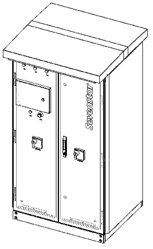
  • Heat radiating structure of outdoor type inverter cabinet body and outdoor type inverter cabinet body
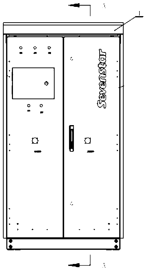
  • Heat radiating structure of outdoor type inverter cabinet body and outdoor type inverter cabinet body
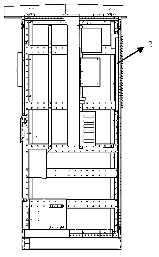
  • Heat radiating structure of outdoor type inverter cabinet body and outdoor type inverter cabinet body

Examples


Embodiment Construction

[0026] The specific implementation manners of the present invention will be further described in detail below in conjunction with the accompanying drawings and embodiments. The following examples are used to illustrate the present invention, but are not intended to limit the scope of the present invention.

[0027] Such as Figure 1-9 As shown, the heat dissipation structure of the outdoor inverter cabinet provided by the present invention includes: an inverter cabinet top cover 1 , an inverter cabinet back panel 2 , an air duct 3 , a radiator 4 , and a fan 5 .

[0028] Wherein, there are ventilation holes 11 and 13 at the lower front and rear bends of the top cover 1 of the inverter cabinet respectively. The rear ventilation holes 11 , 13 are separated by an internal partition 12 .

[0029] Ventilation holes are provided on the back panel 2 of the inverter cabinet; the air duct 3 has an air outlet 31 . The top cover 1 and the air duct 3 completely separate the hot air and ...


PUM


Abstract

The invention provides a heat radiating structure of an outdoor type inverter cabinet body. The heat radiating structure of the outdoor type inverter cabinet body comprises a top cover (1) of the inverter cabinet body, a backboard (2) of the inverter cabinet body, an air duct (3), a radiator (4) and a fan (5). The top cover is arranged on the top of the inverter cabinet body. The top cover comprises an air inlet hole (11) formed in the front bending position below the top cover, an air outlet hole (13) formed in the back bending position below the top cover and a partition board (12), wherein the partition board is arranged in the middle of the top cover and separates the air inlet hole (11) and the air outlet hole (13). The backboard is arranged on the back of the inverter cabinet body, a vent hole is formed in the backboard, the air duct is arranged inside the inverter cabinet body and provided with an air outlet (31), the radiator is arranged below the air outlet (31), and the fan is arranged below the radiator. The invention further provides the outdoor type inverter cabinet body which comprises the heat radiating structure.

Description

technical field [0001] The invention relates to a heat dissipation structure of an outdoor inverter cabinet and an outdoor inverter cabinet with the heat dissipation structure. Background technique [0002] Outdoor photovoltaic inverters must solve the problems of waterproof, dustproof, and heat dissipation. Different manufacturers have different solutions. Many manufacturers add fans and radiators to the inverter cabinet to dissipate heat from the inverter heat source. Some Manufacturers open ventilation holes on the door panels, but the ventilation holes need to be waterproof and dustproof; the filter at the through holes has a certain blocking effect on the wind force of the fan, which will inevitably reduce the air volume and reduce the inverter’s operating efficiency. Heat dissipation effect: Some manufacturers place the fan at the bottom of the cabinet to blow air to the radiator, and the inverter as a whole enters the air from the bottom and exits from the top, so tha...

Claims


Application Information

Patent Timeline
IPC IPC(8): H05K7/20H05K5/02H02M7/42
Inventor 任晓娜刘建芳
Owner BEIJING SEVENSTAR ELECTRONICS CO LTD
Learn More