

Engine and piston
An engine and piston technology, applied in the direction of engine components, machines/engines, pistons, etc., can solve problems such as difficult post-processing, and achieve the effect of not easily damaged and cracked
- Summary
- Abstract
- Description
- Claims
- Application Information
AI Technical Summary
Problems solved by technology
Method used
Image

Examples
Embodiment approach 1
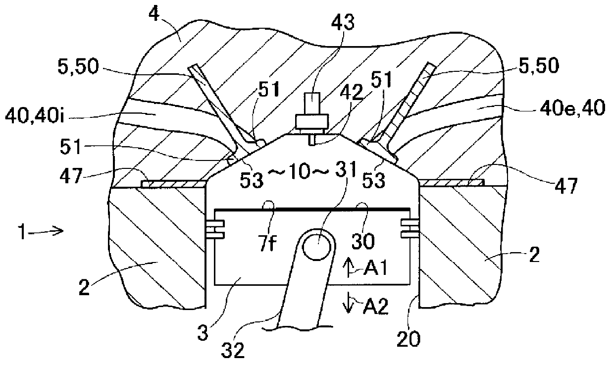
[0043] figure 1 and figure 2 The concept of Embodiment 1 is schematically shown. figure 1 A cross section near the combustion chamber 10 of the engine 1 is schematically shown. Engine 1 is a piston internal combustion engine. figure 1 and figure 2 It's just a conceptual drawing, and doesn't specify the details. The engine 1 includes a cylinder block 2 having a hole 20, a piston 3 fitted in the hole 20 so as to reciprocate in the directions of arrows A1 and A2 to form a combustion chamber 10 on the top surface 30 side, and a piston 3 which closes the combustion chamber 10 and is connected with The cylinder head 4 of the valve hole 40 communicated with the combustion chamber 10 and the valve 5 that opens and closes the valve hole 40 . The valve hole 40 has an intake valve hole 40i and an exhaust valve hole 40e that can communicate with the combustion chamber 10 . The cylinder head 4 is attached to the cylinder block 2 via a gasket 47 . The cylinder block 2, the cylinder...
Embodiment approach 2
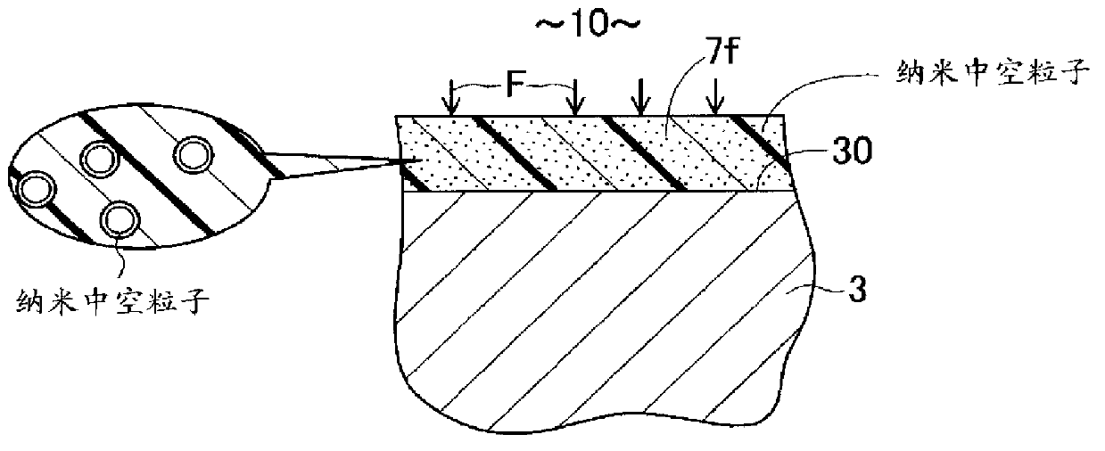
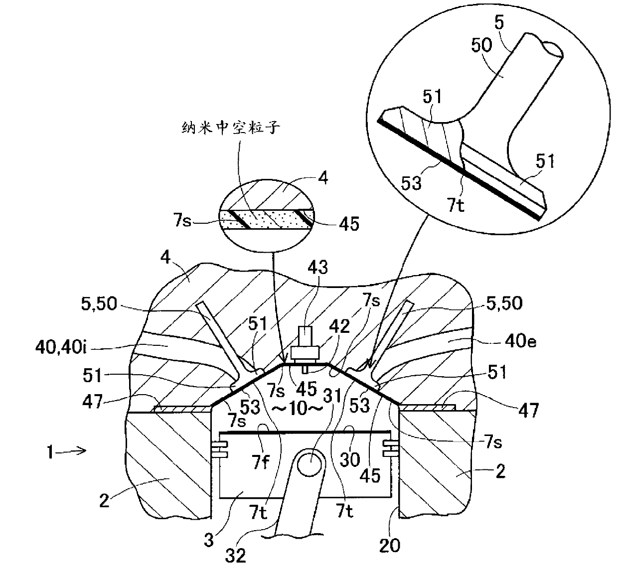
[0053] image 3 Embodiment 2 is shown. This embodiment has basically the same configuration as Embodiment 1, and has operational effects. image 3 A cross section near the combustion chamber 10 of the engine 1 is schematically shown. The wall surface 30 facing the combustion chamber 10 in the piston 3, that is, the top surface 30 is coated with a first heat insulating coating film 7f. Moreover, the wall surface 45 facing the combustion chamber 10 in the cylinder head 4 is coated with the second heat insulating coating film 7s. Since 7 f of 1st heat insulating coating films and 7 s of 2nd heat insulating coating films are formed, the heat insulation property of the combustion chamber 10 improves. Depending on the circumstances, as long as the second heat insulating coating film 7s is formed on the wall surface 45 of the cylinder head 4, the first heat insulating coating film 7f may be abolished. In addition, the surface roughness of the wall surface after application of the...
Embodiment approach 3
[0055] This embodiment has basically the same structure as Embodiments 1 and 2, and has effects, so it can be applied to Figure 1 ~ Figure 3 . A first heat insulating coating film 7 f is applied to the top surface 30 which is a wall surface of the piston 3 facing the combustion chamber 10 . Moreover, the wall surface 45 facing the combustion chamber 10 in the cylinder head 4 is coated with the second heat insulating coating film 7s. In addition, a third heat insulating coating film 7t is also formed on the valve face 53 facing the combustion chamber 10 in the valve 5 . In this way, the first heat insulating coating film 7f is formed on the top surface 30 of the piston 3, the second heat insulating coating film 7s is formed on the wall surface 45 facing the combustion chamber 10 in the cylinder head 4, and the second heat insulating coating film 7s is formed on the wall surface 45 facing the combustion chamber 10 in the valve 5. A third heat insulating coating film 7t is for...
PUM
| Property | Measurement | Unit |
|---|---|---|
| thickness | aaaaa | aaaaa |
| thickness | aaaaa | aaaaa |
| thickness | aaaaa | aaaaa |
Abstract
Description
Claims
Application Information