Anti-friction bearing

A rolling bearing and rolling element technology, applied in rolling contact bearings, bearings, bearings in rotating motion, etc., can solve problems such as damage, unfavorable bending of guiding and retaining elements, and achieve the effect of simple and safe installation

Inactive Publication Date: 2013-09-25
SCHAEFFLER TECH AG & CO KG
View PDF11 Cites 7 Cited by
  • Summary
  • Abstract
  • Description
  • Claims
  • Application Information

AI Technical Summary

Problems solved by technology

Guide and retaining elements can

Method used


Image

  • Anti-friction bearing
  • Anti-friction bearing
  • Anti-friction bearing

Examples


Embodiment Construction

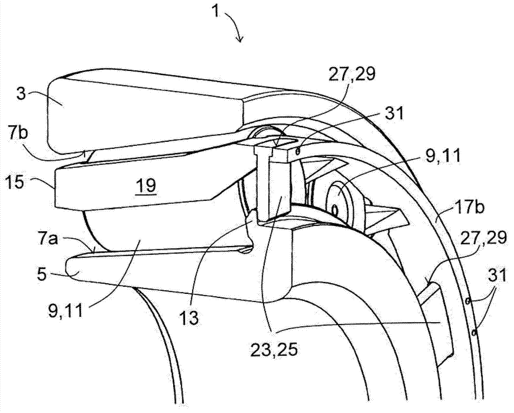
[0026] figure 1 Accordingly, a rolling bearing 1 is shown, which is designed here as a tapered roller bearing. The rolling bearing 1 comprises a bearing outer ring 3 and a bearing inner ring 5 into which several raceways 7a, 7b are introduced. A plurality of conical rolling elements 9 are arranged between the raceway 7a of the bearing inner ring 5 and the raceway 7b of the bearing outer ring 3, figure 1 You can see two of them.

[0027] The tapered rollers 11 roll on the raceways 7a, 7b of the bearing rings 3, 5 . In order to guide the rolling of the tapered roller 11 on the raceway 7a, 7b, on the side of the raceway 7a of the bearing inner ring 5 (in figure 1There is a very large rib 13 on the structure on the right side in the middle. The rib 13 extends from the bearing inner ring 5 radially outwards towards the bearing outer ring 3 . The bearing outer ring 3 is designed without ribs in this exemplary embodiment. In addition, the bearing inner ring 5 has no ribs on its...


PUM


Abstract

The invention relates to an anti-friction bearing (1) having a bearing outer ring (3), a bearing inner ring (5) and a plurality of rolling bodies (9) which are arranged between the bearing outer ring (3) and the bearing inner ring (5), are held at predefined spacings from one another by a bearing cage (15) and roll on raceways (7a, 7b) of the bearing rings (3, 5), of which at least one raceway is delimited by a rim (13), wherein the bearing cage (15) has two cage side rings (17a, 17b) and a plurality of cage webs (19) which connect the cage side rings (17a, 17b), and in which at least one guiding and holding element (23) extends from the bearing cage (15) towards the rim (13) and engages axially behind the rim (13). According to the invention, at least one opening (27) is formed in one of the cage side rings (17b), in which opening (27) the at least one guiding and holding element (23) is fastened. As an alternative to this, in an anti-friction bearing (1') according to the invention, an additional ring (33) is fastened to one of the cage side rings (17b), with which additional ring (33) the guiding and holding element (23) is formed in one piece. The proposed construction avoids the risk that the guiding and holding element (23) is damaged during the assembly of the anti-friction bearing (1).

Description

technical field [0001] The invention relates to a rolling bearing with a bearing outer ring, a bearing inner ring and a plurality of rolling elements arranged between the bearing outer ring and the bearing inner ring, held at a predetermined distance from each other by a bearing cage and rolling on raceways of bearing rings, at least one of which is delimited by ribs, wherein the bearing cage has two cage side rings and a plurality of cage webs connecting the cage side rings, and wherein , at least one guide and retaining element extends from the bearing cage towards the rib and engages axially against the rib. Background technique [0002] Rolling bearings of the type described here are known per se. During their assembly, the problem arises that after the bearing cage holding the rolling elements has been moved onto the bearing inner ring, these components must not fall off one another and the rolling elements must be kept in the optimum assembly position. For rolling be...

Claims


Application Information

Patent Timeline
IPC IPC(8): F16C33/46
CPCF16C33/4605F16C19/364F16C33/4664F16C33/583F16C43/04F16C2226/40F16C2300/02
Inventor 亚历山大·舒尔茨迈克尔·诺伊曼托斯滕·施莱格尔
Owner SCHAEFFLER TECH AG & CO KG
Why Eureka
Try Eureka