
Method and apparatus for transformer diagnosis

The technology of a diagnostic device and a diagnostic method, which is applied in the field of power transformers, can solve the problems that are not enough for transformer diagnosis

Active Publication Date: 2013-09-25
HITACHI ENERGY LTD
View PDF7 Cites 19 Cited by
  • Summary
  • Abstract
  • Description
  • Claims
  • Application Information

AI Technical Summary

Problems solved by technology

However, even without employing this simplification, the accuracy of the results obtained by the proposed method is usually not sufficient for the purpose of transformer diagnostics

Method used


Image

  • Method and apparatus for transformer diagnosis
  • Method and apparatus for transformer diagnosis
  • Method and apparatus for transformer diagnosis

Examples


Embodiment Construction

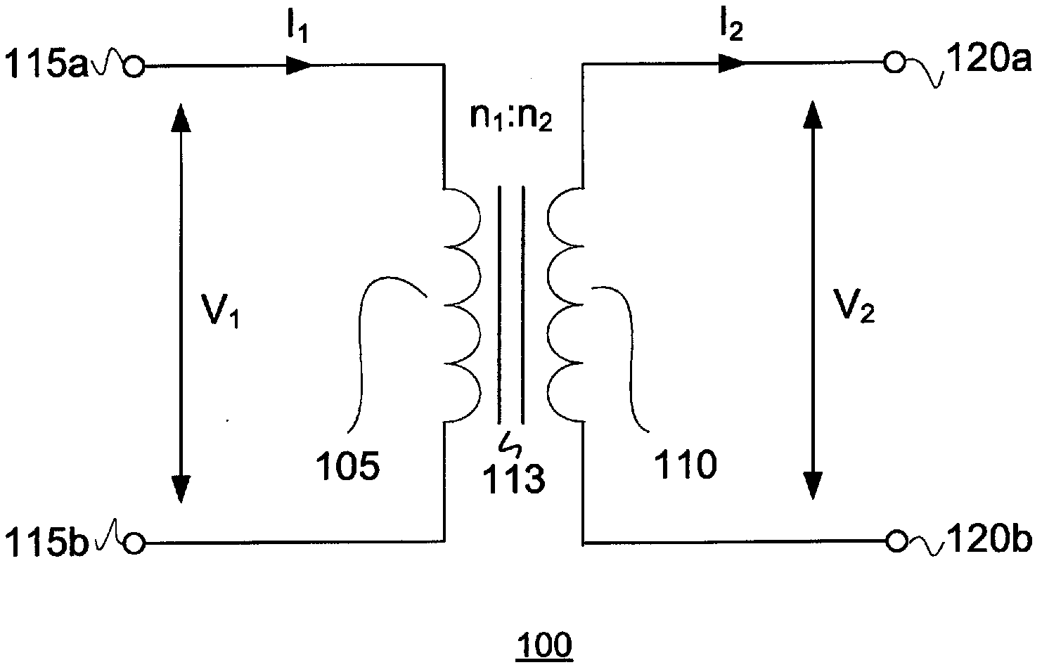
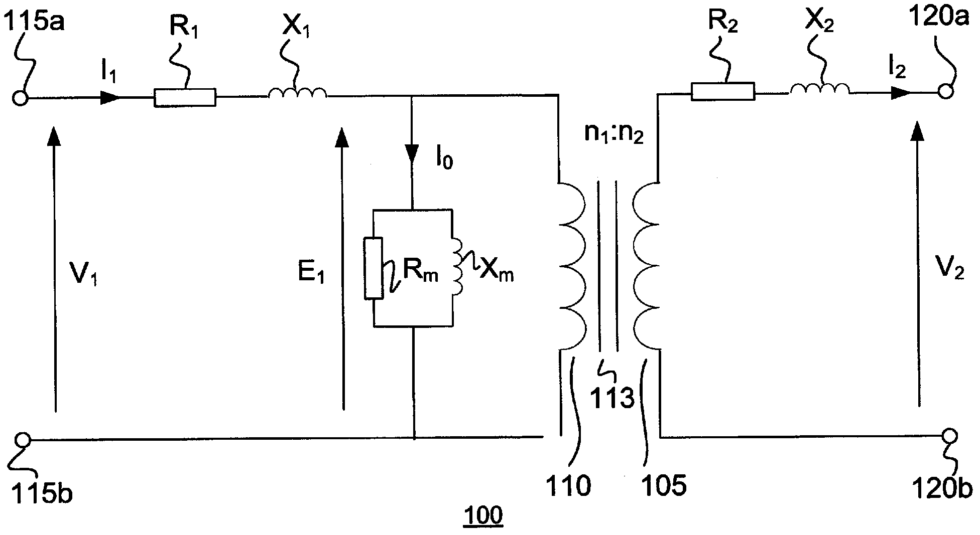
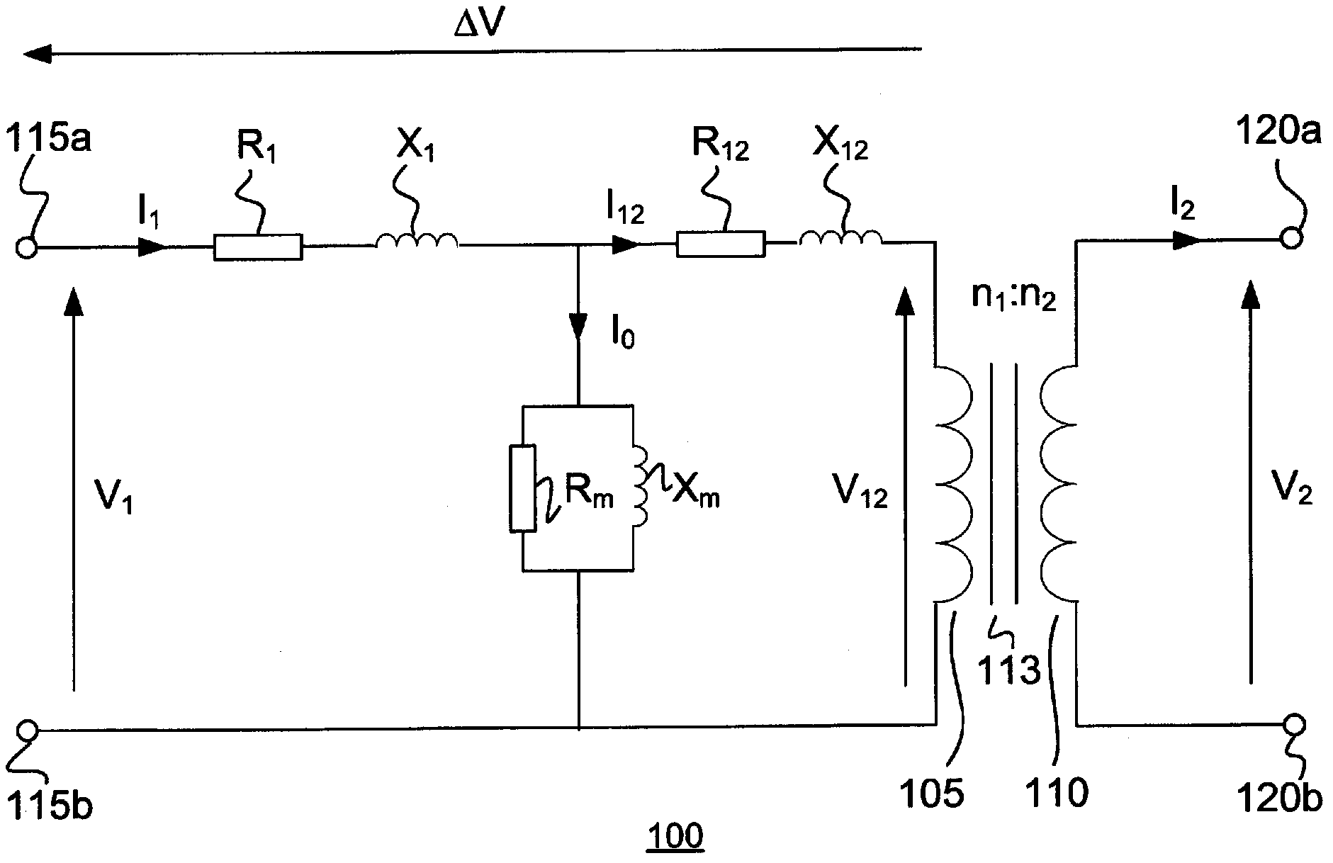
[0042] In power transmission and distribution systems, transformers are often used to convert one voltage level to another and / or to provide galvanic isolation between different sections of the power transmission system. figure 1 A schematic illustration of a transformer 100 is shown in . figure 1 The transformer 100 includes a first winding 105, a second winding 110, a transformer core 113, a first pair of winding terminals 115a, 115b connected to the first winding 105, and a second pair of winding terminals 120a, 120b connected to the second winding 110. The voltage across the first winding 105 is labeled V 1 , and the voltage across the second winding 110 is labeled V 2 , while the current through the first winding 105 is marked I 1 and the current through the second winding 110 is marked I 2 . The number of turns of the first winding is marked n 1 , and the number of turns on the second winding is marked n 2 , in the following the ratio n 1 / n 2 is called the turns...


PUM


Abstract

The present invention relates to a transformer diagnosis apparatus and method which can advantageously be used for on-line diagnosis of a transformer, and by which transformer properties may be monitored and / or determined. The diagnosis method comprises collecting, for at least two different transformer loads, measurements of a current being indicative of the transformer load, as well as measurements of at least one further transformer AC signal. The method further comprises deriving, from the collected measurements, at least two values of a quantity which depends on a transformer property as well as on transformer load; and determining, from the derived values, a set of coefficient(s) of a relation for how said quantity is expected to vary with transformer load. The method further comprises using the determined coefficient (s) in performing a diagnosis of the transformer.

Description

technical field [0001] The present invention relates to the field of power transformers, and in particular to on-line diagnosis of transformers. Background technique [0002] Transformers generally form the main part of a power transmission system, offering the possibility to convert one voltage level to another. Transformers in power transmission systems often represent a huge investment and are usually not manufactured unless ordered. In situations where a transformer in a power transmission system needs to be replaced, the replacement is often a lengthy process. In order to prevent situations in which the transformer needs to be replaced during a rescue operation, it is desirable to detect early problems so that necessary repairs or planned replacements can be performed. [0003] Transformer on-line monitoring systems are designed to detect and indicate deviations in transformer characteristics during transformer operation that can indicate deterioration of transformer ...

Claims


Application Information

Patent Timeline
Patent Type & Authority Applications(China)
IPC IPC(8): G01R31/02G01R31/62G01R31/72
CPCG01R31/62G01R31/52G01R31/72G01R19/00G01R31/00G01R31/50G01R29/20G01R35/02H02H7/04
Inventor N·阿贝威克拉玛T·本特森
Owner HITACHI ENERGY LTD
Learn More