Initial position detection for a sensorless, brushless dc motor

A sensing circuit and phase technology, applied in starting devices, electronic commutators, etc., can solve problems such as unreliability, small size, unsuitable for direct application, and increased cost of sensors

Inactive Publication Date: 2013-09-25
TEXAS INSTR INC
View PDF9 Cites 12 Cited by
  • Summary
  • Abstract
  • Description
  • Claims
  • Application Information

AI Technical Summary

Problems solved by technology

However, these sensors add cost and are often unreliable, so it is desirable to eliminate them, similar to what is achieved in small motor applications (ie, hard drives)
There are some issues associated with large scale applications (i.e. maintaining initial position at startup) that may make direct application of small scale solutions inapplicable

Method used


Image

  • Initial position detection for a sensorless, brushless dc motor
  • Initial position detection for a sensorless, brushless dc motor
  • Initial position detection for a sensorless, brushless dc motor

Examples


Embodiment Construction

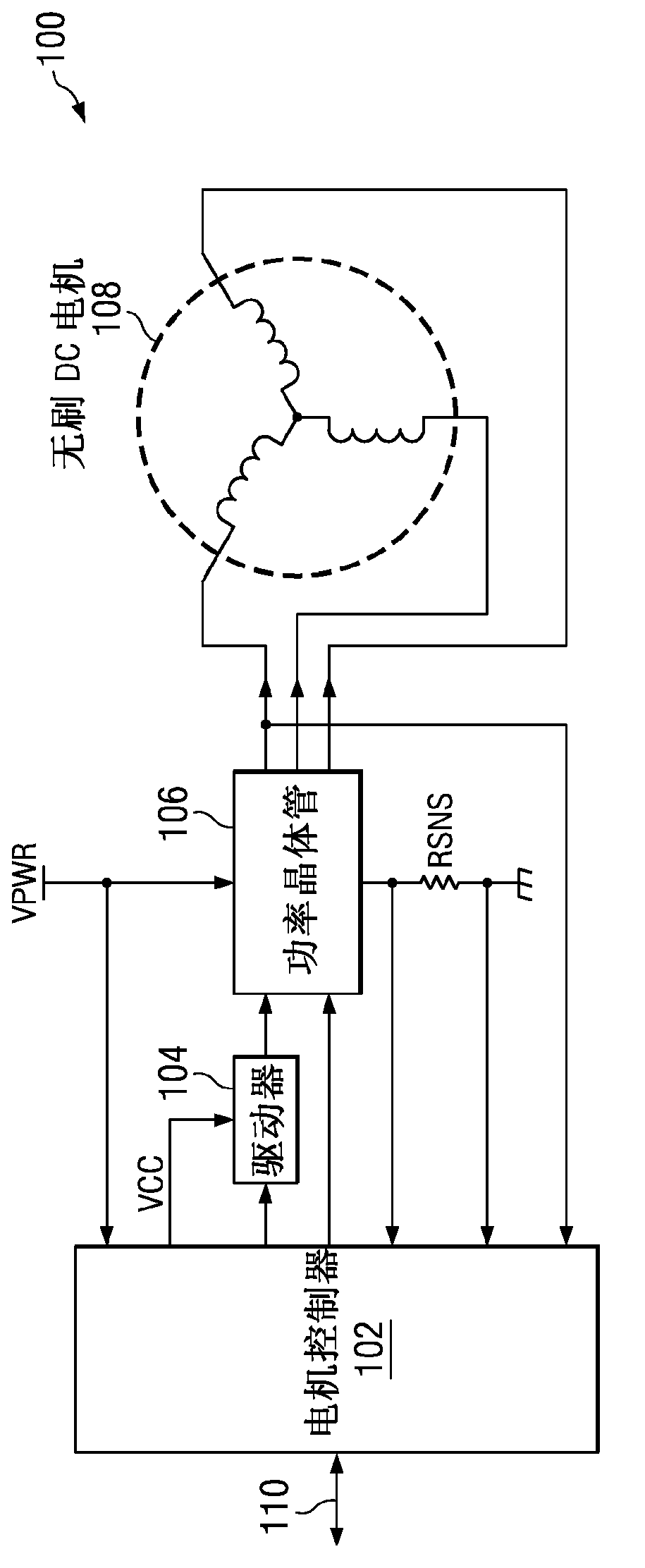
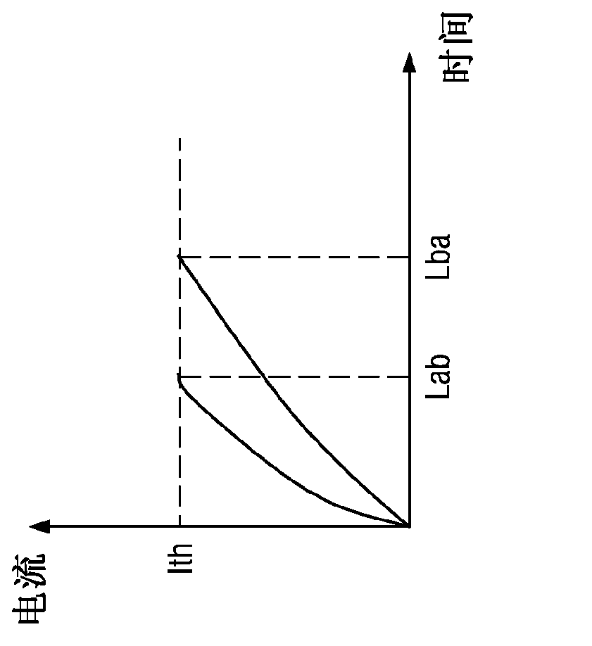
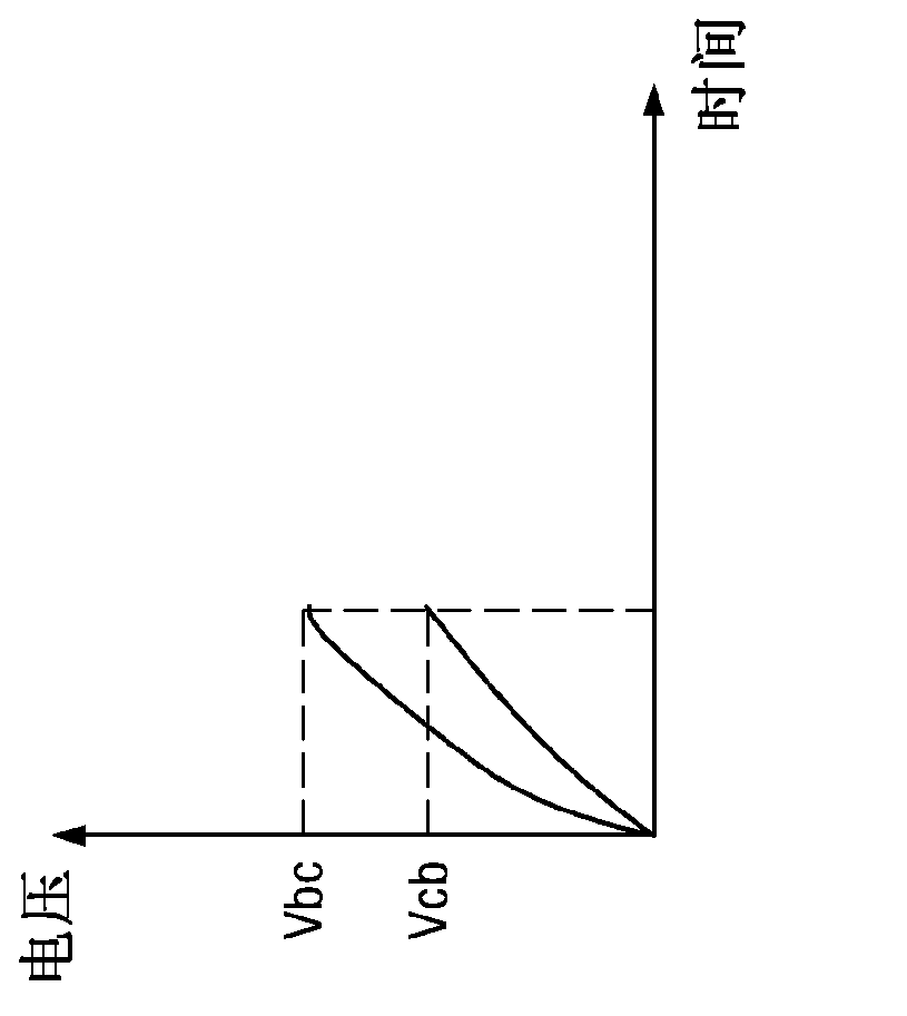
[0028] figure 1 An exemplary system 100 is shown. The system 100 generally includes a motor controller 102 , an actuation circuit (which may include a driver 104 , a power transistor 106 , and a sense resistor RSNS), and a sensorless brushless DC motor 108 . When determining the initial position of the motor 108, the motor controller 102 (which may control itself, or be programmed through a communication channel 110, which may use one or more communication architectures, such as inter-integrated circuit (I 2 C) bus or Universal Asynchronous Receiver / Transmitter (UART)) generates voltage pulses that engage each pair of phases of the motor 108 . The current traversing each pair of phases of the motor 108 can be sensed with a sense resistor RSNS (which may be, for example, 500 mΩ) and should be small enough to maintain an initial position large enough for detection (ie, about lasts about 1ms). Specifically, the motor controller 102 can measure the rise times of these currents...


PUM


Abstract

A system (100) has a motor controller (102), an actuation circuit (104, 106, RSNS), and a sensorless, brushless DC motor (108). 2N voltage pulses are generated for 2N pairs of phases of motor (108). A current is sensed for each of the 2N pairs of phases, to determine a phase inductance from the sensed current for each of the 2N pairs of phases. The determined phase inductances are compared to a look-up table to determine the initial position of motor (109).

Description

technical field [0001] The present invention relates generally to initial position detection, and more particularly to initial position detection for sensorless brushless direct current (DC) motors. Background technique [0002] For most large motor applications (ie, vehicles), Hall effect sensors are used to determine rotor position. However, these sensors add cost and are often unreliable, so it is desirable to eliminate them, similar to what is achieved in small motor applications (ie, hard disk drives). There are some issues associated with large scale applications (ie maintaining initial position at startup) that may make direct application of small scale solutions unsuitable. Therefore, what is needed is a method and / or apparatus for determining an initial position of a motor while maintaining the initial position. [0003] Some examples of conventional methods and / or apparatus are described in US Patent Nos. 5,028,852, 7,072,778, 5,191,270, and 7,334,854. Contents...

Claims


Application Information

Patent Timeline
Patent Type & Authority Applications(China)
IPC IPC(8): H02P6/16
CPCH02P6/20H02P6/22
Inventor X·王
Owner TEXAS INSTR INC
Why Eureka
Try Eureka