Robot Assembly Fixture

A technology of manipulators and jigs, which is applied in the direction of manufacturing tools, metal processing, and metal processing equipment. It can solve problems such as incorrect insertion of needle-shaped plug-ins, potential safety hazards in products, and increased fatigue, achieving low cost and low labor intensity. , to avoid the effect of assembly errors

Active Publication Date: 2016-05-11
WUXI MATEX PRECISION
View PDF7 Cites 1 Cited by
  • Summary
  • Abstract
  • Description
  • Claims
  • Application Information

AI Technical Summary

Problems solved by technology

The assembly of the needle-shaped insert 65 and the part 6 is mostly done manually. This assembly method is labor-intensive and low-efficiency, and due to increased fatigue, assembly errors may occur, and the needle-shaped insert may not be correctly inserted into the through hole at the bottom of the stepped hole. 64, the product has potential safety hazards; a small number of highly automated machinery has complex structures, high costs, and difficult maintenance

Method used


Image

  • Robot Assembly Fixture
  • Robot Assembly Fixture
  • Robot Assembly Fixture

Examples


Embodiment Construction

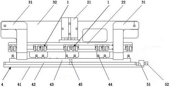
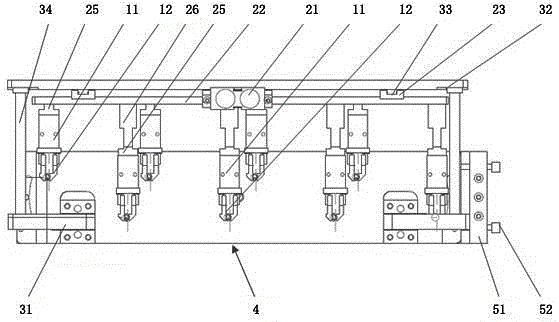
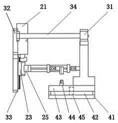
[0018] Such as Figure 1 to Figure 3 As shown, the manipulator assembly jig includes a manipulator device and a base 4. The base 4 is provided with several sets of positioning parts for fixing the parts to be processed. The number of groups of devices and manipulator devices is equal to the number of positioning parts. Each group of manipulator devices includes manipulators 1 equal to the number of plug-ins to be inserted into the parts to be processed. The fixed plate 22 is connected and driven by the lifting device 21 to move up and down. The lifting device 21 Supported on the base 4 by a support structure, the manipulator 1 includes a gripper 12 and a robot arm 11 , and the robot arm 11 drives the gripper 12 to perform back and forth telescopic movements.

[0019] The support structure includes a support plate 32 and a support frame 31. The lifting device 21 is fixed on the support plate 32. The support frame 31 is fixed on both lateral sides of the base 4 and is fixedly co...


PUM


Abstract

The invention provides a manipulator-assembling jig, which can effectively lower the labor intensity and improve the production efficiency, has a simple and reasonable structure and low device cost and is simple to maintain. The manipulator-assembling jig comprises manipulator devices and a pedestal and is characterized in that a plurality of groups of positioning pieces for fixing parts to be machined are arranged on the pedestal, the manipulator devices are installed on a fixed plate, a plurality of groups of manipulator devices are arranged on the fixed plate, the group number of the manipulator devices is equal to that of the positioning pieces, each group of manipulator device comprises manipulators with the number which is equal to that of plug-ins needing to be plugged into the parts to be machined, the fixed plate is connected with and driven by a lifting device to upwards and downwards move, the lifting device is supported on the pedestal through a supporting structure, the manipulator comprises a clamping jaw and a mechanical arm, and the clamping jaw is driven to make forward and backward telescopic movement by the mechanical arm.

Description

technical field [0001] The invention relates to the technical field of auxiliary equipment for parts assembly, in particular to a manipulator assembly jig. Background technique [0002] A kind of automobile part 6, its structure is as Figure 4 and Figure 5 As shown, the part 6 is a hollow part with a chamber 61 inside, and two joints 62 protruding outward from the upper part. A stepped hole 63 communicating with the chamber 61 is arranged in the joint part 62 and is located at the bottom of the stepped hole 63. A needle-shaped insert 65 is inserted in the through hole 64 of the through hole 64. The parts 6 are provided with fixing parts 67 and 68 on both lateral sides, and the fixing parts 67 and 68 are provided with threaded holes 66. The assembly of the needle-shaped insert 65 and the part 6 mostly adopts the method of manual filling, which is labor-intensive and low-efficiency, and may cause assembly errors due to increased fatigue, and the needle-shaped insert may not...

Claims


Application Information

Patent Timeline
Patent Type & Authority Patents(China)
IPC IPC(8): B23P19/04
Inventor 的场年昭
Owner WUXI MATEX PRECISION
Why Eureka
Try Eureka