
Roller for paper machining machine

A processing machine and roller technology, applied in the direction of mechanical processing/deformation, etc., can solve the problems of slippage, increase of production cost, material running out, etc., and achieve the effects of avoiding material running out, improving wear resistance and reducing costs

Inactive Publication Date: 2013-10-02
KUNSHAN JIESHENG PRECISION HARDWARE
View PDF5 Cites 1 Cited by
  • Summary
  • Abstract
  • Description
  • Claims
  • Application Information

AI Technical Summary

Problems solved by technology

A kind of roller announced by Chinese patent CN 202526800 U, it is lined with inner tube in the outer tube, is provided with packing layer outside the outer tube, has reduced wear and tear to a certain extent, but has improved production because of adding two packing layers like this. At the same time, during the operation of the upper and lower rollers, it is easy to slip, resulting in the phenomenon of material running

Method used


Image

  • Roller for paper machining machine

Examples


Embodiment Construction

[0013] In order to make the object, technical solution and advantages of the present invention clearer, the present invention will be further described in detail below in conjunction with the accompanying drawings and embodiments. It should be understood that the specific embodiments described here are only used to explain the present invention, not to limit the present invention.

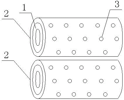
[0014] see figure 1 , figure 1 It is a structural schematic diagram of the present invention.

[0015] The drum used on paper processing machines includes an upper drum and a lower drum, and the upper and lower drums are rolled from seamless steel pipes; there is an outer tube 1 on the upper drum, and the outer surface of the outer tube 1 is A composite layer 2 is provided, and a composite layer 2 is also provided on the lower roller. The composite layer 2 contains silicon carbide or corundum, which is used to reduce wear and improve wear resistance;

[0016] The upper drum and the lower drum ar...


PUM


Abstract

The invention relates to a roller for a paper machining machine. The roller comprises an upper roller body and a lower roller body. An outer pipe is arranged on the upper roller body. A composite layer is arranged on the outer surface of the outer pipe. A composite layer is further arranged on the lower roller body. Through holes are formed in both the upper roller body and the lower roller body. By the adoption of the roller for the paper machining machine, the wear resisting effect is improved, the material running phenomenon is avoided, cost is reduced, and water and energy are saved.

Description

technical field [0001] The invention relates to the field of cylinders, in particular to a cylinder used on a paper processing machine. Background technique [0002] At present, the roller on the paper processing machine is composed of upper and lower rollers. The upper roller only has an outer tube made of seamless steel pipe, without inner tube and outsourcing material, and the lower roller is made of plastic. A kind of roller announced by Chinese patent CN 202526800 U, it is lined with inner tube in the outer tube, is provided with packing layer outside the outer tube, has reduced wear and tear to a certain extent, but has improved production because of adding two packing layers like this. At the same time, during the operation of the upper and lower drums, it is easy to slip, resulting in the phenomenon of material running. Contents of the invention [0003] The purpose of the present invention is to overcome the deficiencies of the prior art and provide an economical...

Claims


Application Information

Patent Timeline
IPC IPC(8): B31F1/00
Inventor 周升华
Owner KUNSHAN JIESHENG PRECISION HARDWARE
Learn More