A Tension Control Mechanism for Printing Machine Cloth

A tension control mechanism and printing machine technology, applied in printing machines, rotary printing machines, printing, etc., can solve problems affecting printing effects, etc., and achieve the effect of adjusting the tension and solving the tension

Active Publication Date: 2015-08-26
SHENZHEN TEXTALK GRAPHIC TECH
View PDF5 Cites 2 Cited by
  • Summary
  • Abstract
  • Description
  • Claims
  • Application Information

AI Technical Summary

Problems solved by technology

Since the stretching length of knitted fabric and elastic fabric changes with the change of tension, the existing tensioning mechanism cannot realize the adjustment of the tension force. Therefore, after the cloth is printed, due to the disappearance of the tension force, Causes the graphics printed on the cloth to change, thus affecting the printing effect

Method used


Image

  • A Tension Control Mechanism for Printing Machine Cloth
  • A Tension Control Mechanism for Printing Machine Cloth
  • A Tension Control Mechanism for Printing Machine Cloth

Examples


Embodiment Construction

[0023] Below, in conjunction with accompanying drawing and specific embodiment, the present invention is described further:

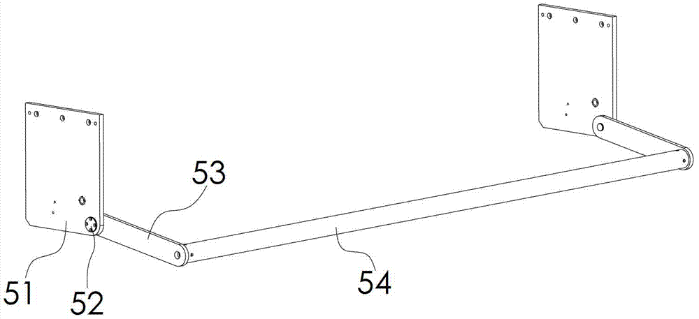
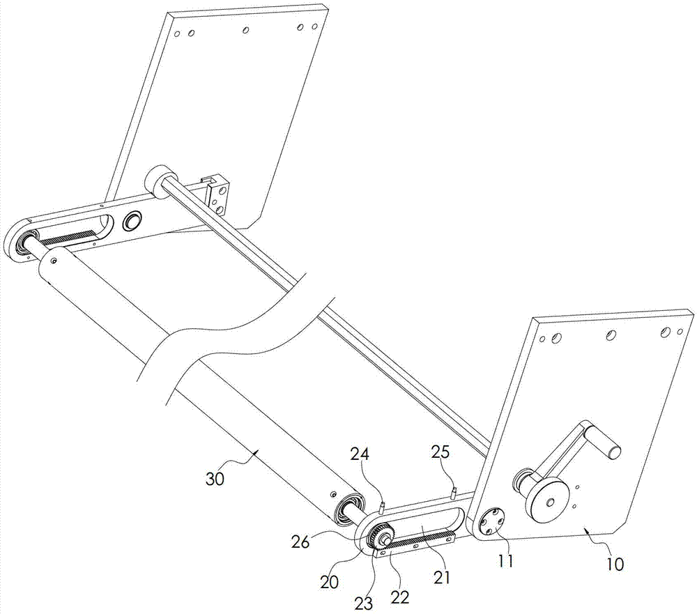
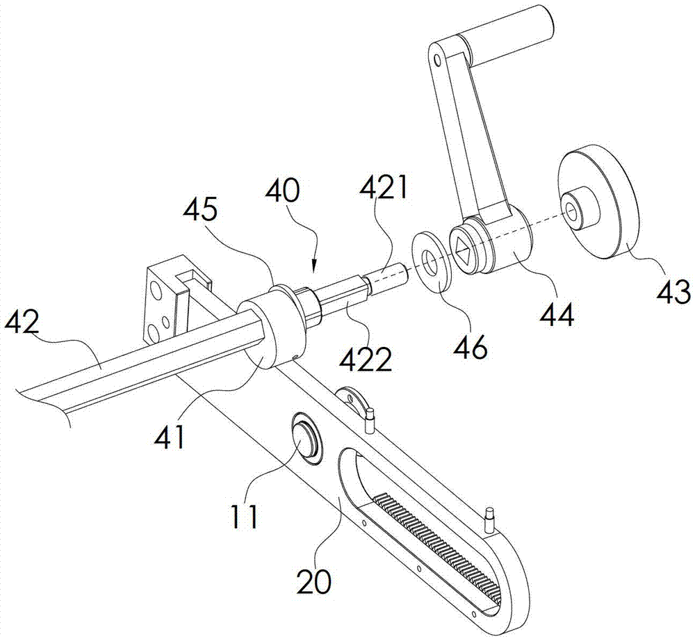
[0024] see figure 2 , 3 , 4, is the tension control mechanism of a kind of printing machine cloth of the present invention, comprises fixed plate 10, swing arm 20, tension roller assembly 30 and angle adjustment assembly 40, and fixed plate 10 is used as the installation basis of the whole mechanism, and swing arm 20 passes through A pivot 11 is pivotally connected to the fixed plate 10, and the swing arm 20 is provided with a chute 21 extending along its length direction and positioned outside the pivot 11. The chute 21 has a built-in chute 21 that can move along the length direction of the chute 21. Bearing 26, the diameter of the outer ring of the bearing 26 is equivalent to the width of the chute 21, which is limited in the chute 21 and can roll in the chute 21; the upper part of the swing arm 20 is also provided with a first limit switch 24 and a...


PUM


Abstract

A tension control mechanism of cloth of a printing machine comprises fixing plates, swinging arms, a tension roller component, and angle adjustment components, wherein each swinging arm is pivoted on each fixing plate by a pivot; a sliding groove is formed in each swinging arm, and internally provided with a rolling component capable of moving in a length direction of the sliding groove; first limit switches and second limit switches are arranged on the swinging arms; signal input ends of the first limit switches and the second limit switches are connected with a controller controlling a cloth feeding motor of the printing machine; the tension roller component is positioned at the outer side end parts of the swinging arms; the end parts of the tension roller component are pivoted on the rolling components; and the angle adjustment components are used for driving the inner side ends of the swinging arms to allow the swinging arms to rotate relative to the fixing plates. According to the mechanism, a tension roller slides along the swinging arms to trigger the different limit switches, correspondingly controls the on and off of the cloth feeding motor, and realizes automatic cloth feeding. Since angles of the swinging arms are adjustable, and the swinging arms can be fixed at the adjusted angles, tension force of the tension roller on the cloth is adjustable and can be kept constant; and the cloth tension is realized effectively.

Description

technical field [0001] The invention relates to a tension control mechanism for cloth of a printing machine. Background technique [0002] The tensioning mechanism is an important part of the printing machine. Its main function is to tension the substrates such as cloth to facilitate the transportation of the cloth and to make the cloth flat when printing graphics. [0003] see figure 1 , the existing tensioning mechanism comprises a fixed plate 51, a swing arm 53 and a tension roller 54, the inner end of the swing arm 53 is pivotally connected to the fixed plate 51 by a pivot 52, and the tension roller 54 is connected to the side of the swing arm 53 At the outer end, during the tensioning process of the tensioning mechanism, the swing arm 53 rotates around the pivot 52 to form different rotation angles. Under the pulling of the cloth, the tension roller 54 exerts a tension force on the cloth that changes with the sinusoidal law. When the swing arm 53 is placed in a ve...

Claims


Application Information

Patent Timeline
Patent Type & Authority Patents(China)
IPC IPC(8): B41F13/02
Inventor 王首斌李景锋刘慧锋
Owner SHENZHEN TEXTALK GRAPHIC TECH
Why Eureka
Try Eureka