Self-adaptive multistage pressure relief controlled press liquid filling device

A liquid filling device and self-adaptive technology, applied in the direction of fluid pressure actuating device, mechanical equipment, servo motor components, etc., can solve the problems such as the need to increase the filling speed, the pressure distribution imbalance, and the limited liquid flow rate, and achieve the unloading process. Stable and fast, uniform pressure distribution in the flow channel, avoiding the effect of turbulence and impact

Active Publication Date: 2013-10-02
FUJIAN HAIYUAN AUTOMATIC EQUIP CO LTD
View PDF10 Cites 2 Cited by
  • Summary
  • Abstract
  • Description
  • Claims
  • Application Information

AI Technical Summary

Problems solved by technology

This method increases the cost and the system is complicated. If the electronic control error causes the liquid filling device to open under high pressure, it will cause serious damage
Pressure relief through the pilot spool (for example, refer to patent 200520069161.2) can improve efficiency, but it can only achieve single-stage pressure relief and the stability of the pressure relief process is insufficient, especially in high-pressure conditions, it is easy to form strong impacts, which affects the reliability of the system.
[0006] 2) There is less optimization of the flow channel of the valve body, and the filling speed needs to be improved
The optimization of the liquid filling channel structure is the key to increasing the liquid filling speed, but there are few related designs (such as the reference patent WO02062545A1), and the main way is to form a diversion channel to increase the liquid filling speed by matching the upper end of the liquid filling device with the upper beam. The diversion design involving the entire flow channel (such as the diversion structure under the liquid filling device), thus limiting the further improvement of the liquid flow rate
[0007] 3) Under the condition of large flow rate, the reliability of the liquid-filled spool is insufficient
If the design of the flow channel is unreasonable, the pressure distribution will easily be unbalanced during the opening and closing process of the valve core, which will cause the valve core to move and impact, which will seriously affect the reliability of the liquid filling process and may cause equipment damage
The structural design of the existing (patented) liquid filling device does not involve the influence of the flow pressure distribution, and it is easy to cause unreliable operation of the valve core under the super large flow rate

Method used


Image

  • Self-adaptive multistage pressure relief controlled press liquid filling device
  • Self-adaptive multistage pressure relief controlled press liquid filling device
  • Self-adaptive multistage pressure relief controlled press liquid filling device

Examples


Embodiment Construction

[0043] Best practice:

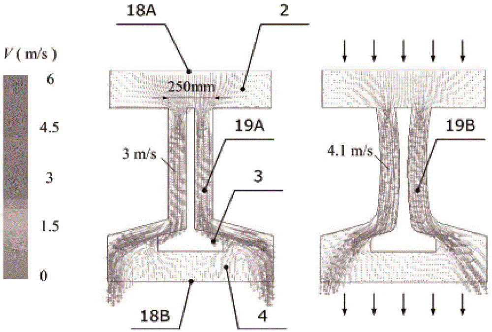
[0044] refer to figure 1 , schematically represents the assembly of an adaptive multi-stage pressure relief control press liquid filling device in a hydraulic press according to the present invention. The liquid filling device 3 arranged between the liquid filling tank 2 and the main cylinder 4 can be used in equipment such as the hydraulic machine 1, and plays an important role in the two main working conditions of the main cylinder 4 filling and returning. During the liquid filling process, by controlling the upper end of the oil cylinder 6 to enter the oil, as the main oil cylinder 4 falls, the liquid in the liquid filling tank 2 quickly enters the main oil cylinder 4 through the opened liquid supply device 3, and pushes the main cylinder piston 5 downward. After the pressing process is completed, the main oil cylinder 4 needs to be returned. In this process, the high pressure in the main oil cylinder 4 needs to be removed first, and then the liquid...


PUM


Abstract

The invention discloses a liquid supply device of a press. The liquid supply device is a device arranged between a liquid filling tank and a main oil cylinder, and comprises an inner valve core, a middle valve core, an outer valve core and the like, wherein the middle valve core is provided with a damping hole; and the outer valve core is provided with a draining hole. In the return stroke of the main oil cylinder, the inner valve core is opened, and oil in the main oil cylinder enters the liquid filling tank through the damping hole and the draining hole to realize primary pressure relief; and when the pressure of the main oil cylinder falls to a preset pressure respectively, the middle valve core and the outer valve core are opened automatically to realize secondary and tertiary pressure relief, and meanwhile, the oil is returned rapidly. The entire process is characterized by high speed, stability and high adaptability. Moreover, a multi-structure three-dimensional flow guide design is adopted for the profile surface of the valve cores and wall surfaces according to the working characteristics of the press, so that high oil flow speed and good pressure distribution are realized. Due to the adoption of a self-adaptive multistage unloading structure and a full-flow-channel flow guide design, a high-pressure unloading process is stable and efficient, and high oil flow speed and low hydraulic power are realized; and the liquid supply device is particularly suitable for high-pressure and high-flow working conditions.

Description

technical field [0001] The invention relates to a liquid filling device for a hydraulic system of a press, in particular to a press liquid filling device for self-adaptive multi-stage pressure relief control. [0002] Background technique [0003] The rapid movement of the main cylinder is the key to ensure the efficient work of large hydraulic machines, which mainly depends on the filling device, especially the filling valve. When the movable crossbeam goes down quickly, the oil in the low-pressure filling tank quickly flows into the main oil cylinder through the device; on the contrary, when the movable crossbeam quickly returns, the high-pressure oil in the main cylinder is quickly discharged into the low-pressure filling tank through the device after the pressure is relieved. The fast forward, pressure maintaining, pressure relief and return actions of the main cylinder must be completed with the participation of the liquid filling device, so the structure of the liquid...

Claims


Application Information

Patent Timeline
Patent Type & Authority Applications(China)
IPC IPC(8): F15B13/02
Inventor 陈晖李良光陈远刘胜辉杜恒
Owner FUJIAN HAIYUAN AUTOMATIC EQUIP CO LTD
Why Eureka
Try Eureka