Clamp device of lamp wick automatic molding machine

An automatic forming machine and material clamping technology, which is applied in the direction of turning off electric tubes/lights, etc., can solve the problems of low efficiency, inconvenient operation, complicated material clamping device, etc., and achieve the effect of convenient use and simple structure

Active Publication Date: 2013-10-02
德清县人杰电光源材料厂
View PDF5 Cites 0 Cited by
  • Summary
  • Abstract
  • Description
  • Claims
  • Application Information

AI Technical Summary

Problems solved by technology

However, this type of operation has the following defects: one is that manual operation is used, and the efficiency is low; Copper wire is melted and welded, so there is a danger to human safety
At present, there are certain automatic wick welding machines on the market, but the clamping device of this type of wick welding machine is relatively complicated, inconvenient to operate, and prone to problems, which is not conducive to long-term work

Method used


Image

  • Clamp device of lamp wick automatic molding machine

Examples


Embodiment Construction

[0010] Combine below figure 1 Specific description embodiment:

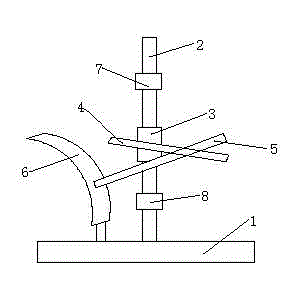
[0011] A clamping device for a wick automatic molding machine, comprising a base 1, the base 1 is provided with a vertical rod 2, and the feature is that the vertical rod 2 is provided with a sliding sleeve 3, and the sliding sleeve 3 A driven half-clamp 4 is connected to the top, and the driven half-clamp 4 is movably connected with an active half-clamp 5. The base 1 is provided with a curved riser 6, and the curved riser 6 gradually moves from the lower end to the upper end. Away from the pole 2, the active half clamp 5 can slide on the curved riser 6, and when the active half clamp 5 is located at the lower end of the curved riser 6, the active half clamp 5 and the driven half clamp 4 are closed, When the active half clamp 5 is located at the upper end of the curved vertical plate 6, the active half clamp 5 and the driven half clamp 4 are separated.

[0012] Preferably, the upper end of the vertical rod 2 is...


PUM


Abstract

The invention belongs to of the technical field of lamp appliances, particularly relates to a clamp device of a lamp wick automatic molding machine, and discloses a clamp device of a lamp wick automatic molding machine, which includes a base, wherein an upright post is arranged on the base; a sliding sleeve is arranged on the upright post; a driven half clamp is connected onto the sliding sleeve; the driven half clamp is movably connected with a driving half clamp; a curved surface vertical plate is arranged on the base; the curved surface vertical plate gradually gets away from the upright post from the lower end to the upper end; the driving half clamp can slide on the curved surface vertical plate; when the driving half clamp is positioned at the lower end of the curved surface vertical plate, the driving half clamp and the driven half clamp are closed; when the driving half clamp is positioned at the upper end of the curved surface vertical plate, the driving half clamp and the driven half clamp are separated. The clamp device is simple in structure and convenient to use, and satisfactorily enables a finished lamp wick to be taken out of a working rotary table and placed in other positions.

Description

technical field [0001] The invention belongs to the technical field of lamps and appliances, and in particular relates to a clamping device of an automatic wick forming machine. Background technique [0002] In the process of making lamps and lanterns, the production of wick is the most complicated. The wick is made of glass tube and copper wire. The process of making it is to insert the glass tube into the copper wire, and then weld the two ends of the glass tube to the copper wire by welding, so that the glass tube is sealed. The current manufacturing process of the wick is done by hand. Firstly, the glass tube is inserted into the copper wire by hand, and then the two ends of the glass tube are fused and welded on the copper wire manually to achieve the purpose of sealing the glass tube. However, this kind of operation has the following defects: one is that manual operation is used, and the efficiency is low; Copper wire is melted and welded, so there is a danger to h...

Claims


Application Information

Patent Timeline
IPC IPC(8): H01J9/40C03C27/02
Inventor 唐玉杰
Owner 德清县人杰电光源材料厂
Why Eureka
Try Eureka