Aerosol generating system with means for disabling consumable

A technology for generating systems and stopping devices, applied to electric heating devices, transportation and packaging, tobacco, etc.

Active Publication Date: 2013-10-02
PHILIP MORRIS PROD SA
View PDF5 Cites 33 Cited by
  • Summary
  • Abstract
  • Description
  • Claims
  • Application Information

AI Technical Summary

Problems solved by technology

[0003] Existing aerosol generating systems include the above-mentioned aerosol generating systems. This aerosol generating system does have many advantages, but there are still improvements in the design structure, especially in the operation of the liquid storage part.

Method used


Image

  • Aerosol generating system with means for disabling consumable
  • Aerosol generating system with means for disabling consumable

Examples


Embodiment Construction

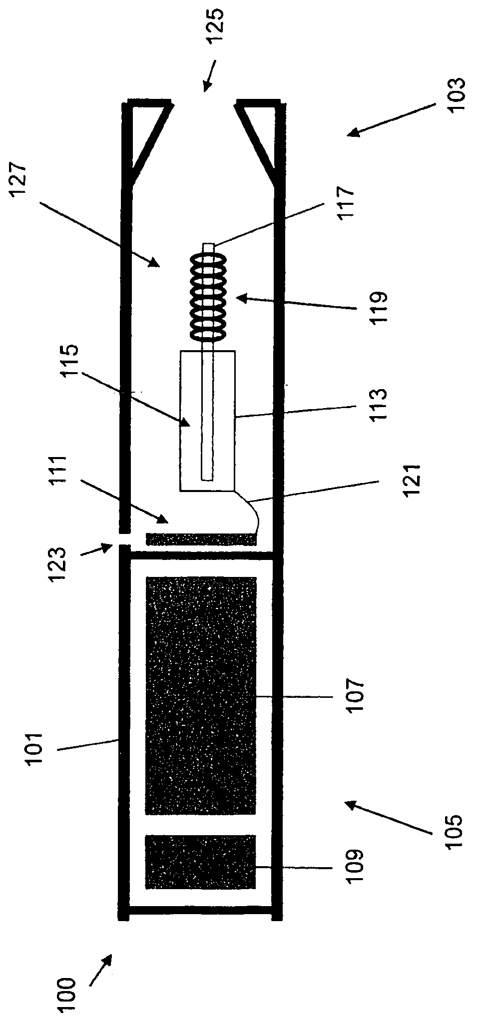
[0053] figure 1 An example of an electro-aerosol generating system having a liquid reservoir is shown. exist figure 1 Among them, the system is a smoke generation system. figure 1 The smoke generating system 100 includes a housing 101 having a mouthpiece end 103 and a body end 105 . At the main body end, a power source in the form of a battery 107 and electrical control circuits 109 are provided. The smoke detection system 111 is also arranged to cooperate with the electronic control circuit 109 . At the mouthpiece end, a liquid reservoir in the form of a cartridge 113 containing a liquid 115 , a capillary wick 117 and a heater 119 are provided. Note that in figure 1 The heater is only schematically shown in . exist figure 1 In the exemplary embodiment shown, one end of the capillary wick 117 protrudes into the cartridge 113 and the other end of the capillary wick is surrounded by a heater 119 . The heater is connected to the electric control circuit through the wiring...


PUM

PropertyMeasurementUnit
lengthaaaaaaaaaa

Abstract

There is provided an aerosol generating system comprising: a storage portion for storing an aerosol-forming substrate, an aerosol generating element for generating an aerosol from the aerosol-forming substrate, control circuitry in communication with the storage portion, and disabling means within the storage portion for rendering the storage portion inoperable in the aerosol generating system in response to a disable signal from the control circuitry. There is also provided a method in an aerosol generating system comprising a storage portion for storing aerosol-forming substrate, an aerosol generating element for generating an aerosol from the aerosol-forming substrate, control circuitry in communication with the storage portion and disabling means within the storage portion configured to render the storage portion inoperable in the aerosol generating system in response to a disable signal from the control circuitry, the method comprising: sending a disable signal from the control circuitry to the disabling means following a determination that an amount of the aerosol-substrate in the storage portion is below a threshold level or following a determination of a malfunction in the system.

Description

technical field [0001] The present invention relates to aerosol generating systems. In particular, the present invention relates to an aerosol-generating system in which the aerosol-generating substrate is a liquid and is contained in a liquid reservoir. Background technique [0002] Document WO2007 / 078273 discloses an electronic cigarette generating appliance. The liquid is stored in a container connected to the heated evaporator, and the battery power supplies the electric power to the heated evaporator through a series of small holes. The heater is in the form of a spiral wound electric heater mounted on an electrically insulating support. In use, the user's mouth actuates the heater to turn on the power. The user draws on the nozzle, causing air to be drawn through the holes in the container, which then coats the heater vaporizer, enters the nozzle, and then enters the user's mouth. [0003] Existing aerosol generating systems include the above-mentioned aerosol gene...

Claims


Application Information

Patent Timeline
Patent Type & Authority Applications(China)
IPC IPC(8): A24F47/00A61L9/03A24F40/10A24F40/53
CPCA24F40/53A24F40/10A24F47/00A61L9/037A61L2209/132A61L2209/135A24D3/17H05B1/02A24F40/40A24F40/50B63C9/115F41H1/02
Inventor J-M·弗利克
Owner PHILIP MORRIS PROD SA
Why Eureka
Try Eureka