Tube bending inner supporting device and tube bending method

A technology for supporting devices and pipes, applied in the field of machining, can solve the problems of difficult to control the forming quality, high mold manufacturing cost, uneven contact between the metal core mold and the inner wall of the pipe, etc. The degree of chemical modification, the cost of manufacture and use are low, and the effect of easy replacement and maintenance

Active Publication Date: 2015-04-01
AVIC BEIJING AERONAUTICAL MFG TECH RES INST
View PDF5 Cites 0 Cited by
  • Summary
  • Abstract
  • Description
  • Claims
  • Application Information

AI Technical Summary

Problems solved by technology

[0003] 1. Due to the difference in the geometric dimensions of the pipes, it is often necessary to customize multiple sets of metal mandrels for a pipe of one specification, and the cost of mold manufacturing is high;
[0004] 2. During the pipe bending process, there will be uneven contact between the metal mandrel and the inner wall of the pipe, which will cause the inner cavity of the pipe to be easily scratched, and prone to forming defects such as wrinkles, and the forming quality is difficult to control;
[0005] 3. In addition, the metal mandrel itself is easy to wear in the tube cavity, which further increases the cost of manufacturing and using the mandrel

Method used


Image

  • Tube bending inner supporting device and tube bending method
  • Tube bending inner supporting device and tube bending method
  • Tube bending inner supporting device and tube bending method

Examples


Embodiment Construction

[0035] The details of the present invention can be understood more clearly with reference to the accompanying drawings and the description of specific embodiments of the present invention. However, the specific embodiments of the present invention described here are only for the purpose of explaining the present invention, and should not be construed as limiting the present invention in any way. Under the teaching of the present invention, the skilled person can conceive any possible modification based on the present invention, and these should be regarded as belonging to the scope of the present invention.

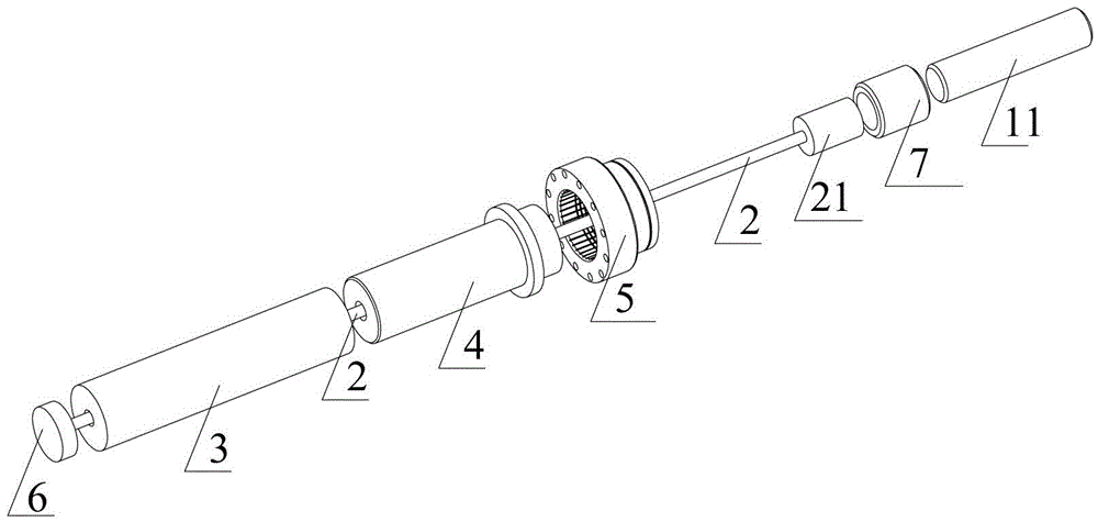
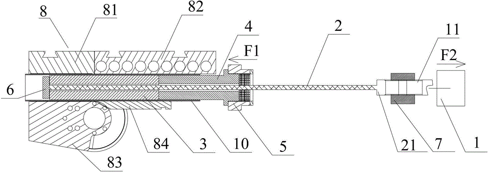
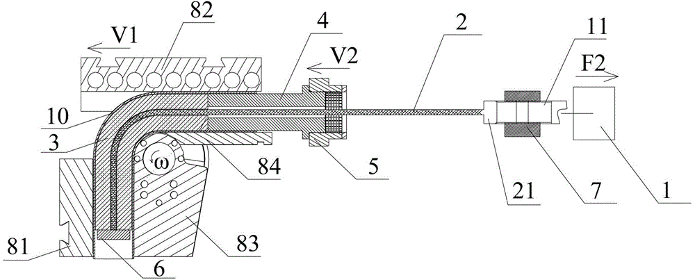
[0036] Please refer to figure 1 , figure 2 , image 3 , are respectively the three-dimensional structure schematic diagram of the pipe bending inner support device of the present invention; the cross-sectional structural schematic diagram installed on the pipe bender before the pipe bending operation; and the cross-sectional structural schematic diagram installed on th...


PUM

PropertyMeasurementUnit
diameteraaaaaaaaaa
yield strengthaaaaaaaaaa

Abstract

The invention discloses a tube bending inner supporting device and a tube bending method. The tube bending inner supporting device comprises a load mechanism, a steel wire rope, an elastic core die, a pushing die and a pushing part. The load mechanism is provided with a stretchy rod which contracts to one side. One end of the steel wire rope is connected with a stretchy end of the stretchy rod and the other end of the steel wire rope is connected with a top disc. The elastic core die, the pushing die and the pushing part sequentially and movably penetrate through the steel wire rope. One end of the elastic core die is connected with the top disc in an abutted mode. The pushing part is detachably connected with the pushing die and retracts through the stretchy rod of the load mechanism. The top disc is matched with the steel wire rope to pull the elastic core die and the pushing die tight, so that the elastic core die expands in an inner cavity of a tube in a radial mode and is fully contacted with the inner wall of the tube. According to the tube bending inner supporting device and the tube bending method, the core die is matched with the inner wall of the tube in a self-adapting mode, crinkling is avoided and manufacturing and use cost can be greatly reduced.

Description

technical field [0001] The invention relates to the field of mechanical processing, in particular to a pipe bending inner support device using an elastic mandrel and a pipe bending method. Background technique [0002] As we all know, the bending and forming of pipes requires the synergy and strict cooperation of multiple molds. During the bending forming process, the clamp block drives the pipe and the bending die to rotate synchronously. Under the action of the clamp block tension, the pipe slides over the bending tangent point, and bends and deforms under the bending moment of the bending plane and contacts the bending die, thus The predetermined bending radius of the pipe is formed, and the bending moment of the pipe will be generated by the resultant force of the pulling force of the clamp on the pipe and the friction between the pipe molds. During the bending process, in order to prevent the defects of wrinkling and excessive cross-section of the pipe, it is necessary...

Claims


Application Information

Patent Timeline
Patent Type & Authority Patents(China)
IPC IPC(8): B21D9/01B21D9/12B21D9/16
Inventor 吴为闫晶张荣霞
Owner AVIC BEIJING AERONAUTICAL MFG TECH RES INST
Why Eureka
Try Eureka