Injection mold for magnetic conduction ring assembly and manufacturing method thereof

A technology of injection mold and manufacturing method, which is applied in the direction of household appliances, other household appliances, gears, etc., can solve the problems of affecting the magnetic field induction effect, reducing the consistency and reliability of sensors, and low mechanical strength, so as to improve consistency and reliability Sexuality, good conduction and distribution, simple stamping process

Active Publication Date: 2016-09-07
杭州新世宝电动转向系统有限公司
View PDF6 Cites 0 Cited by
  • Summary
  • Abstract
  • Description
  • Claims
  • Application Information

AI Technical Summary

Problems solved by technology

[0004] (1) Since the teeth of the upper and lower magnetic conducting rings are relatively placed, the positioning of the magnetic conducting ring through the cooperation of the positioning hole and the guide post is only a positioning in the vertical direction between the upper and lower magnetic conducting rings, while the upper and lower magnetic conducting rings When the rings are placed relative to each other, the teeth are relatively occluded. This positioning method cannot guarantee the accuracy of the alignment of the teeth of the upper and lower magnetic rings, thus affecting the performance of the product.
[0005] (2) In order to realize the positioning between the upper and lower magnetic rings, a positioning hole is provided on the magnetic ring, which hinders the magnetic path on the magnetic ring, makes the magnetic field distribution uneven, and affects the effect of magnetic field induction; Moreover, at the positioning hole, the mechanical strength is also low, and the micro-deformation that will occur when the stress is applied here will cause the magnetic circuit to break, which will affect the effect of magnetic field induction, thereby reducing the consistency and reliability of the sensor, and greatly Reduces the accuracy of the signal delivered by the sensor

Method used


Image

  • Injection mold for magnetic conduction ring assembly and manufacturing method thereof
  • Injection mold for magnetic conduction ring assembly and manufacturing method thereof
  • Injection mold for magnetic conduction ring assembly and manufacturing method thereof

Examples


Embodiment Construction

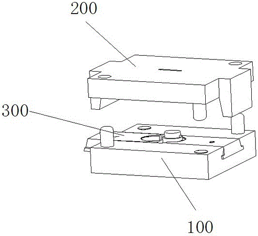
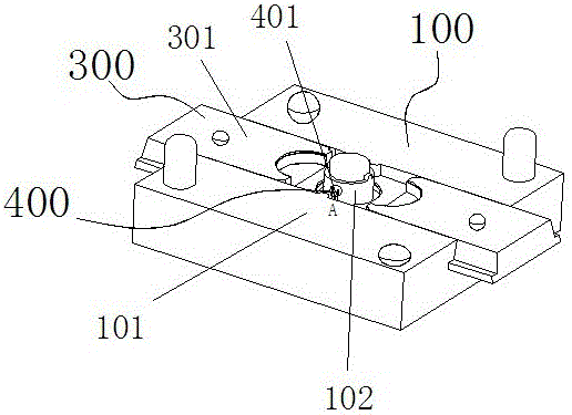
[0049] Such as Figure 1-10 As shown, an injection mold of a magnetic ring assembly includes a lower mold assembly 100 and an upper mold assembly 200 and a positioning mechanism 300 provided on the lower mold assembly, and the lower mold assembly 100 includes a lower mold assembly The mold 101 , the mandrel 102 provided on the lower mold 101 and the guiding device 400 provided on the mandrel 102 , the upper mold assembly 200 includes the upper mold 201 and the injection gate 202 arranged on the upper mold 201 .

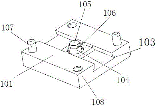
[0050] In this embodiment, the positioning mechanism 300 includes a slider 301 symmetrically arranged on the upper surface of the lower mold 101, and one end of the slider 301 is provided with an open groove 302. When placed, the open groove 302 of the slider 301 is placed opposite , two open grooves 302 form a circle just surrounding the outer end surface of the magnetic conduction ring, which is used to position the magnetic conduction ring; both sides of the slider...


PUM


Abstract

The invention discloses an injection mold for a magnetic conduction ring assembly, comprising a lower mold assembly (100), an upper mold assembly (200) and a positioning mechanism (300) provided on the lower mold assembly (100) , the lower mold assembly (100) includes a lower mold (101), a mandrel (102) provided on the lower mold (101), and a guide device (400) arranged on the mandrel (102), the upper The mold assembly (200) includes an upper mold (201) and an injection gate (202) arranged on the upper mold (201). The invention also discloses a manufacturing method for processing the magnetic conduction ring assembly through the above-mentioned injection mold, which has no holes for positioning, accurate positioning of the upper and lower magnetic conduction rings, simple processing technology, and good performance of the manufactured product.

Description

technical field [0001] The invention relates to a magnetic conducting ring assembly, in particular to an injection mold used for manufacturing the magnetic conducting ring assembly and a manufacturing method thereof. Background technique [0002] For electronic products, in order to protect the internal components, the injection molded products used as the shell are required to have a certain rigidity; especially for some product components, it is necessary to connect the various components through injection molding and have a certain rigidity. [0003] For the magnetic ring assembly in the non-contact hall type torque sensor, the existing manufacturing method of the magnetic ring assembly is also through injection molding, wherein the positioning method of the magnetic ring assembly is provided with a guide post on the lower mold assembly, and the The magnetic ring is provided with a positioning hole, and the magnetic ring is positioned through the cooperation of the positi...

Claims


Application Information

Patent Timeline
Patent Type & Authority Patents(China)
IPC IPC(8): B29C45/33B29C33/30B29L15/00
Inventor 周龙龙蔡黎明王朝久周珑胡明路
Owner 杭州新世宝电动转向系统有限公司
Why Eureka
Try Eureka