Tail structure of dry-type expansion mold
A mold and dry technology, applied in the field of dry expansion mold tail structure, can solve the problems of reduced product quality, increased joints of finished products, large noise pollution, etc., achieves short adjustment time, simple enlargement or reduction, and solves adjustment difficulties Effect
- Summary
- Abstract
- Description
- Claims
- Application Information
AI Technical Summary
Problems solved by technology
Method used
Image
Examples
Embodiment 1
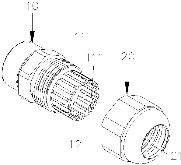
[0018] see figure 1 , which discloses Embodiment 1 of the tail structure of the dry expansion mold of the present invention, including a shrinking nozzle 10 and a lock nut 20 installed on the shrinking nozzle 10 .
[0019] The constriction nozzle 10 is provided with a tube hole (not shown in the figure) that runs through the constriction nozzle. The constriction nozzle 10 is provided with a number of constriction teeth 11 arranged at intervals around one end of the constriction nozzle. hole 12. One end of the shrink mouth 10 is provided with an external thread.
[0020] The lock nut 20 has a lock hole 21 , and the diameter of the lock hole 21 gradually becomes smaller from one end closer to the shrink nozzle 10 to the other end. The lock nut 20 is adjustably locked on the shrink nozzle 10 , wherein the shrink tooth 11 shrinks in the lock hole 21 of the lock nut 20 . In this embodiment, the lock hole 21 of the lock nut 20 is provided with an internal thread, and the lock nut...
Embodiment 2
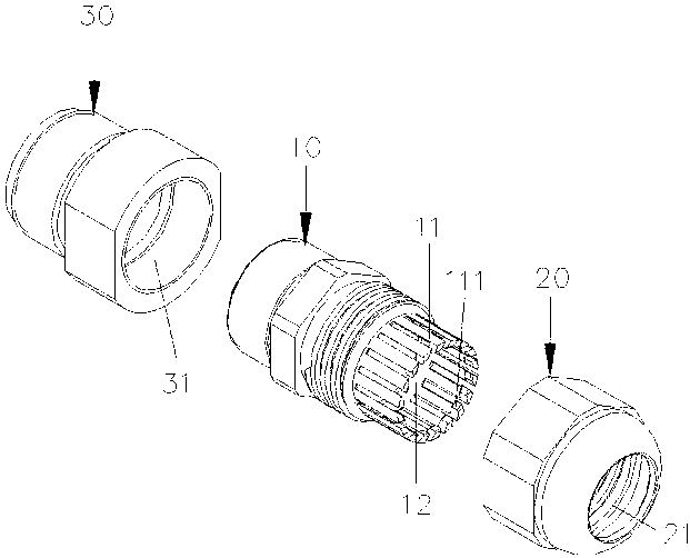
[0027] see figure 2 , which discloses Embodiment 2 of the tail structure of the dry expansion die of the present invention. This embodiment is similar to Embodiment 1, and the difference is that it further includes a reducing sleeve 30, and one end of the reducing sleeve 30 is connected to the expansion die (not shown in the figure). shown), the other end of the reducing sleeve 30 is connected to the constricting nozzle 20, the reducing sleeve 30 has a reducing hole 31, and the reducing hole 31 gradually becomes larger from the end closest to the constricting nozzle 10 to the other end.
[0028] In this embodiment, the reducing sleeve 30 is screwed and fixed to the expansion die, and the other end of the reducing sleeve 30 is screwed and fixed to the shrinking nozzle 10 . Of course, the reducing sleeve 30 can also be integrally formed with the constricting nozzle 10, which can facilitate processing and installation.
PUM
 Abstract
Description
Claims
Application Information
 - R&D
- Intellectual Property
- Life Sciences
- Materials
- Tech Scout
- Unparalleled Data Quality
- Higher Quality Content
- 60% Fewer Hallucinations
Browse by: Latest US Patents, China's latest patents, Technical Efficacy Thesaurus, Application Domain, Technology Topic, Popular Technical Reports.
© 2025 PatSnap. All rights reserved.Legal|Privacy policy|Modern Slavery Act Transparency Statement|Sitemap|About US| Contact US: help@patsnap.com


