feeder

A feeder and feeding tube technology, applied in the field of feeders, can solve the problems of zero point drift and return of the rotor scale, and achieve the effect of solving the air return

Active Publication Date: 2016-08-10
高伦
View PDF8 Cites 0 Cited by
  • Summary
  • Abstract
  • Description
  • Claims
  • Application Information

AI Technical Summary

Problems solved by technology

This structure still has disadvantages. The coal consumption of the rotary kiln is much smaller than the delivery capacity of the coal pump, so the coal in the coal delivery pipe 201 is very little, and there is a large gap in the upper part of the coal delivery pipe 201 provided with the delivery screw, thus forming Without a negative pressure zone, the wind sent into the Venturi tube will return to the rotor scale at the feed inlet from the upper gap of the coal delivery pipe 201, which will still cause the zero point drift of the rotor scale, and the pulverized coal will also return from the gap

Method used


Image

  • feeder
  • feeder
  • feeder

Examples


Embodiment Construction

[0009] The present invention will be described in further detail below through specific implementation examples and in conjunction with the accompanying drawings.

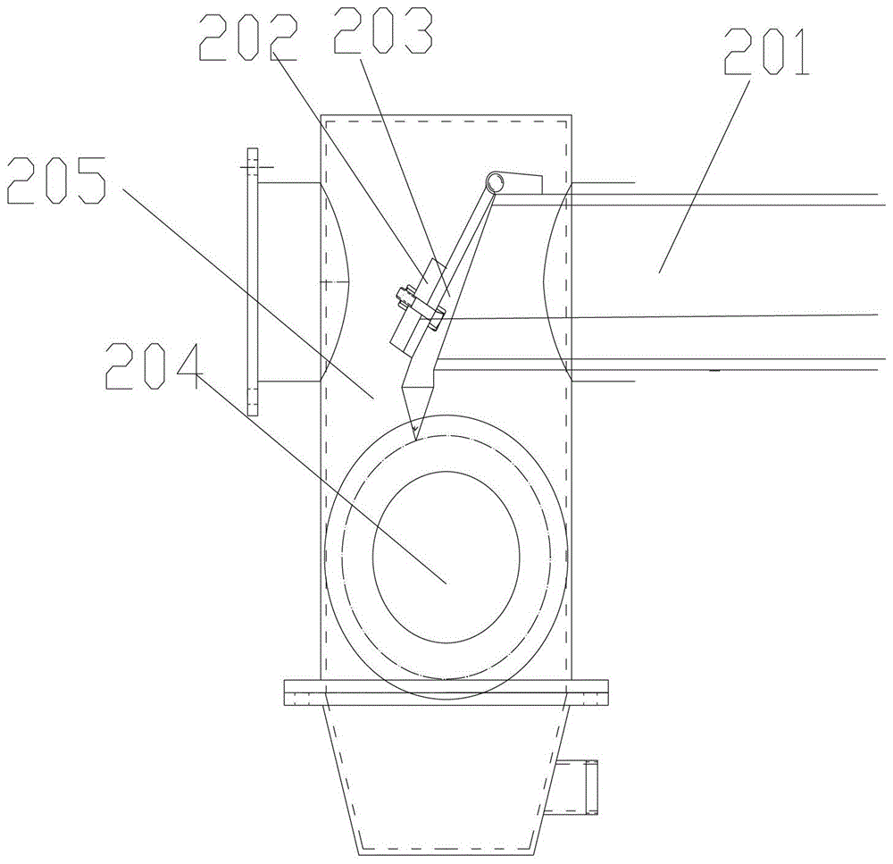
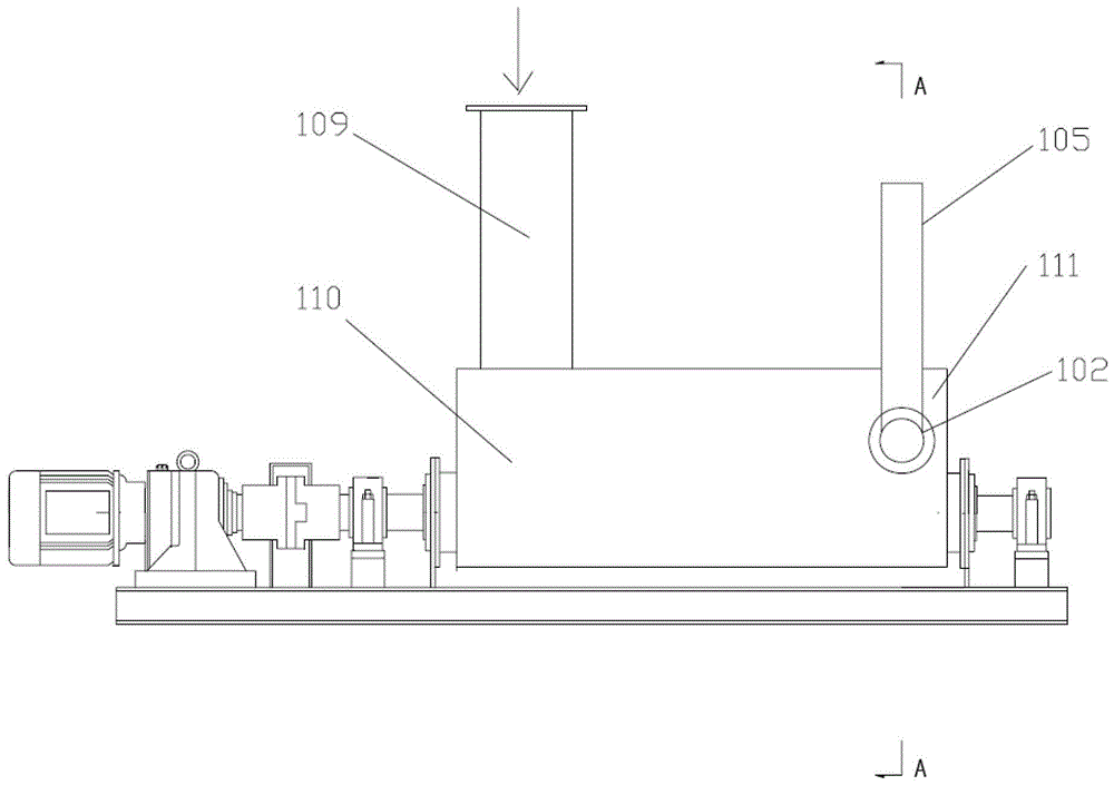
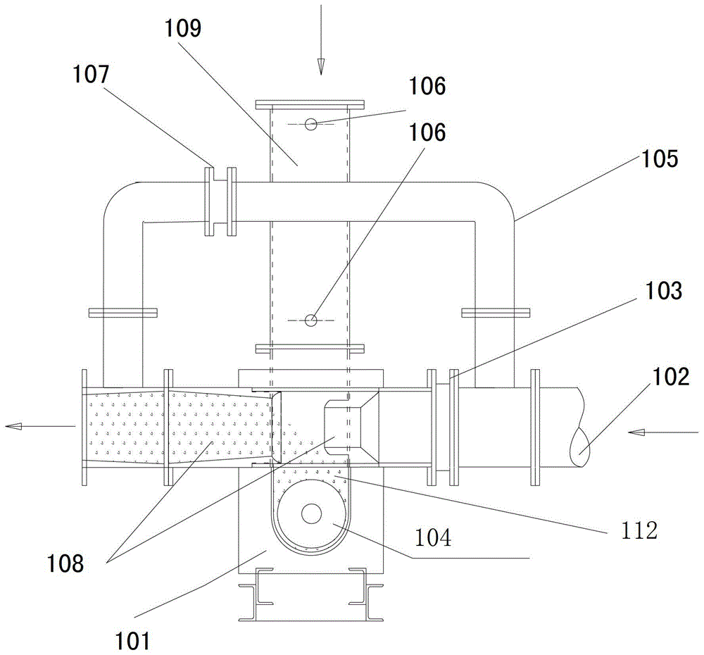
[0010] A feeder, comprising: a feed pipe, the interior of the feed pipe is provided with a variable-pitch conveying screw, and the pitch of the variable-pitch conveying screw from the A end to the B end changes from large to small; the pipe wall of the feed pipe One end is provided with a feed inlet, and the feed inlet is above the A end of the variable-pitch conveying screw; the other end of the feed pipe is provided with a plug-in Venturi tube, and the extension direction of the Venturi tube is in the same direction as the feed pipe. Vertically, the Venturi tube is above the B-end of the variable-pitch conveying screw.

[0011] After the material enters from the feed port, the material is conveyed forward in the feeding pipe through the variable-pitch conveying screw. Since the pitch of the variable-pitch conveyi...


PUM


Abstract

The invention relates to the field of electromechanics, in particular to a feeding machine. The feeding machine comprises a feeding pipe, a variable pitch conveying helix is arranged inside the feeding pipe, and the screw pitch of the variable pitch conveying helix gradually decreases from the A end to the B end of the variable pitch conveying helix. A feed port is formed in one end of the pipe wall of the feeding pipe, and the feed port is placed above the A end of the variable pitch conveying helix. The other end of the feeding pipe is provided with a plug-in type Venturi tube, and the Venturi tube is placed above the B end of the variable pitch conveying helix. When the feeding machine is used, the quantity of materials in a conveying pipe is added, and the problems of wind return and zero drift of a rotor scale instrument are solved.

Description

technical field [0001] The invention relates to the electromechanical field, in particular to a feeding machine. Background technique [0002] In the coal feeding metering system of the rotary kiln, there are often problems such as the zero point drift of the rotor scale instrument caused by the backflow of the metering system to the feed port and the backflow of pulverized coal. The relevant solution is: use the screw coal supply pump (such as figure 1 , as shown) to achieve air-locking and mixing. A slope 203 and a counterweight plate 202 are set in the coal delivery pipe 201. The six-pole electrode is used to run at high speed to make the material enter the mixing bin 205, and then use the principle of the Venturi tube 204 to make the material be blown by high-pressure air. Transport away. This structure still has disadvantages. The coal consumption of the rotary kiln is much smaller than the delivery capacity of the coal pump, so the coal in the coal delivery pipe 201 ...

Claims


Application Information

Patent Timeline
Patent Type & Authority Patents(China)
IPC IPC(8): F23K3/00F23K3/02
Inventor 高伦
Owner 高伦
Why Eureka
Try Eureka