Coupling structure between linear type pulse tube refrigerator and infrared device and manufacturing method for same

A technology of pulse tube refrigerator and coupling structure, which is applied in refrigerators, gas cycle refrigerators, refrigeration and liquefaction, etc., can solve the problems of low refrigeration efficiency, loose structure of the whole machine, and large aspect ratio of cold fingers, etc., to achieve enhanced The effect of reliability, compact structure and efficient transmission

Inactive Publication Date: 2015-03-25
SHANGHAI INST OF TECHNICAL PHYSICS - CHINESE ACAD OF SCI
View PDF6 Cites 2 Cited by
  • Summary
  • Abstract
  • Description
  • Claims
  • Application Information

AI Technical Summary

Problems solved by technology

[0007] Depend on figure 1 It can be seen that the biggest disadvantage of the linear layout of the pulse tube refrigerator is that the cold end heat exchanger is located in the middle of the refrigerator, the two ends are hot ends, and the cold finger has a large aspect ratio, so the coupling with the device is very inconvenient
Improper coupling method will make the overall structure loose, the reliability will be reduced, and the heat leakage will increase sharply, making it difficult to take advantage of the linear pulse tube refrigerator in application
What often happens in practice is that when a linear pulse tube refrigerator with excellent cooling efficiency is coupled with an infrared device, the cold loss caused by improper structural arrangement makes the cooling efficiency of the coupled structure reversed. Unlike the coupling body formed by coaxial or U-shaped pulse tube refrigerators
In addition, another problem that often plagues the application practice is that the linear cold finger with a large aspect ratio leads to a loose structure of the whole machine and a sharp decrease in reliability. This is a problem in special application fields such as aerospace application practice. more prominent problems

Method used


Image

  • Coupling structure between linear type pulse tube refrigerator and infrared device and manufacturing method for same
  • Coupling structure between linear type pulse tube refrigerator and infrared device and manufacturing method for same
  • Coupling structure between linear type pulse tube refrigerator and infrared device and manufacturing method for same

Examples


Embodiment Construction

[0032] Below in conjunction with accompanying drawing and embodiment the specific embodiment of the present invention is described in further detail:

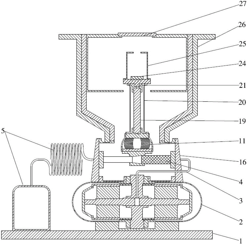
[0033] An invented coupling structure suitable for linear pulse tube refrigerators and infrared devices consists of a main base 1, a compressor 2, connecting pipes 3, a linear pulse tube cold finger 4, a phase modulation mechanism 5, and a cold finger support shell 16. Composed of flexible heat conduction belt assembly 11, columnar cold chain 19, cold chain reinforcement support 20, device cooling platform 21, infrared device 24, cold screen 25, device Dewar 26 and Dewar window 27. The main base 1 serves as the supporting base of the entire coupling structure, and at the same time serves as the heat dissipation structure of the compressor 2 and the phase modulation mechanism 5; the compressor 2 adopts a double-piston opposed structure; The finger 4 and the phase modulation mechanism 5 together form a linear pulse tube refrigera...


PUM


Abstract

The invention discloses a coupling structure between a linear type pulse tube refrigerator and an infrared device and a manufacturing method for the coupling structure between the linear type pulse tube refrigerator and the infrared component. The structure is composed of a main base, a compressor, a connecting tube, a linear type pulse tube cold finger, a phase modulation mechanism, a cold finger supporting outer shell, a flexible heat conduction strip assembly, a columnar cold chain, a cold chain reinforcing support, a device cooling platform, the infrared device, a cold shield and device Dewar. By the adoption of the coupling structure, cold taking can be performed conveniently from the cold end of the linear type pulse tube refrigerator, and the cooling capacity is efficiently transferred from the cold end of the refrigerator to the infrared device. The coupling structure is compact in structure and small in cold losses and has very positive significance for enhancing reliability of the linear type pulse tube refrigerator and the practicability aspect of infrared device cooling.

Description

technical field [0001] The invention belongs to the field of refrigeration and low-temperature engineering, and relates to a pulse tube refrigerator, in particular to a coupling structure and a manufacturing method of a linear pulse tube refrigerator and an infrared device. Background technique [0002] The pulse tube refrigerator is a major innovation of the regenerative cryogenic refrigerator. It cancels the cold end ejector widely used in conventional regenerative cryogenic refrigerators (such as Stirling and G-M refrigerators), and uses heat The phase difference required for refrigeration is achieved by the operation of the end phase adjustment mechanism. The complete elimination of moving parts at the cold end has achieved low vibration, low interference and no wear at the cold end; and through important improvements in structure and phase modulation, in some typical temperature regions, its actual efficiency has reached regenerative low-temperature refrigeration highe...

Claims


Application Information

Patent Timeline
Patent Type & Authority Patents(China)
IPC IPC(8): F25B9/14
CPCF25B2309/1406
Inventor 党海政
Owner SHANGHAI INST OF TECHNICAL PHYSICS - CHINESE ACAD OF SCI
Why Eureka
Try Eureka