Rubber-covered roller laser detector

A detector and laser technology, used in instruments, measuring devices, optical devices, etc., can solve the problems of printed matter wrinkles, large measurement errors, and low product qualification rates.

Inactive Publication Date: 2013-10-09
JINAN POWER RUBBER ROLLER EQUIP
View PDF8 Cites 11 Cited by
  • Summary
  • Abstract
  • Description
  • Claims
  • Application Information

AI Technical Summary

Problems solved by technology

On the contrary, if the geometric dimensions such as the roundness and concentricity of the rubber roller are too large, the rubber roller and the printing material will not be in full contact, and the force will be uniform, and the parts with oversized dimensions will squeeze each other under high-speed operation. And generate a lot of heat, shorten the service life of the rubber roller, and at the same time cause the wrinkles of the printed matter, affecting the printing quality
[0004] In the prior art, the shape and position tolerance of rubber rollers, such as ellipticity, taper, straightness of generatrix and other geometric dimensions, are usually measured manually, or using measuring tools such as vernier calipers and micrometers to measure different parts of rubber rollers. Different operators use different forces when measuring, and the relative positions of the measuring tool and the workpiece are different, so the measurement error is large, the product qualification rate is low, and the work efficiency is low and the work intensity is high, which cannot meet the requirements of modern production lines for product quality control.

Method used


Image

  • Rubber-covered roller laser detector
  • Rubber-covered roller laser detector
  • Rubber-covered roller laser detector

Examples


Embodiment Construction

[0023] The present invention will be further described below in conjunction with the accompanying drawings and embodiments.

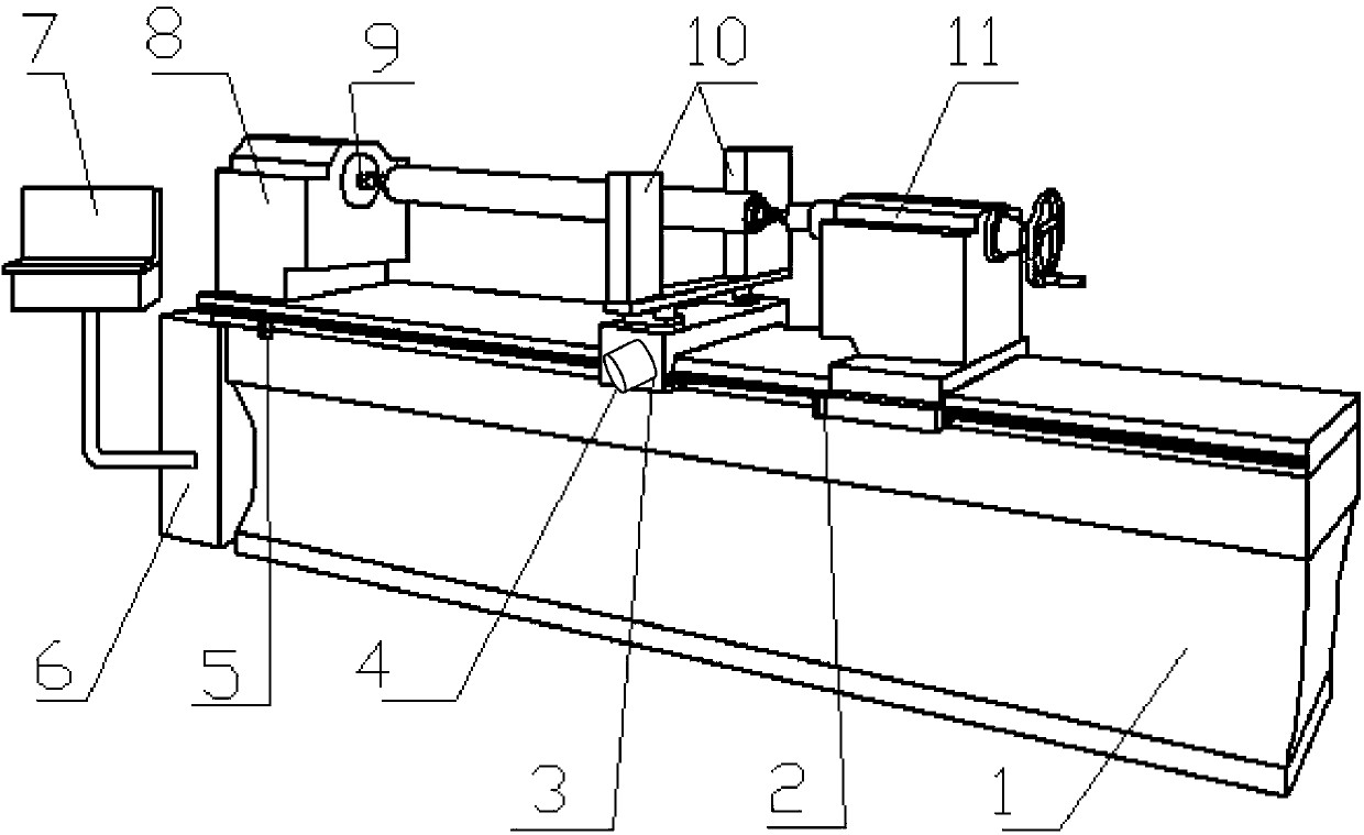
[0024] A rubber roller laser detector, combined with figure 1 , comprising a bed 1 and a tailstock 11, one end of the bed 1 is provided with a headstock 8, the headstock 8 is provided with a workpiece-driven stepping motor 9, and the workpiece-driven stepping motor 9 is connected with the workpiece chuck, One side of bedside box 8 is provided with distribution box 6, operation box 7, and distribution box 6 is electrically connected with operation box 7, and distribution box 6 is connected with power supply, and lathe bed 1 other side is provided with tailstock 11, described A detection frame 4 is provided between the headstock 8 and the tailstock 11, and a laser detector 10 is arranged on the detection frame 4. The detection frame 4 is matched with the bed 1 as a linear guide rail, and the detection frame 4 moves with the measuring head. The stepping m...


PUM


Abstract

The invention discloses a rubber-covered roller laser detector which comprises a lathe bed, wherein a headstock is arranged at one end of the lathe bed, the headstock is provided with a workpiece driving stepping motor, the workpiece driving stepping motor is connected with a workpiece chuck, a distribution box and an operation box are arranged on one side of the headstock, the distribution box is electrically connected with the operation box, the distribution box is connected with a power supply, a tailstock is arranged at the other end of the lathe bed, a detection frame is arranged between the headstock and the tailstock, the detection frame is provided with a group of laser testers, the detection frame is matched with the lathe bed through a linear guide rail to achieve longitudinal moving, the detection frame is connected with a measuring head through a stepping motor which controls longitudinal moving, and the laser testers, the stepping motor driving a workpiece to rotate, the stepping motor driving the measuring head to move, and the operation box are all connected with a PLC system through guide lines.

Description

technical field [0001] The invention relates to the technical field of rubber roller production and detection equipment manufacturing, in particular to a rubber roller laser detector. Background technique [0002] The rubber roller on the printing machine is the most important part. The precision of the rubber roller, such as roundness, concentricity and other geometric dimensions, is too different, and there will be no full contact between the rubber roller and the printing material, and the force will be uniform. The parts that exceed the limit will squeeze each other under high-speed operation and generate a lot of heat, thus shortening the service life of the rubber roller, causing wrinkles in the printed matter, and affecting the printing quality. However, to manufacture high-quality rubber roller products, in addition to relying on high-quality equipment, advanced technology, and the technical level of operators, it also requires precise and scientific testing methods,...

Claims


Application Information

Patent Timeline
Patent Type & Authority Applications(China)
IPC IPC(8): G01B11/00G01B11/02G01B11/08G01B11/24
Inventor 潘建国
Owner JINAN POWER RUBBER ROLLER EQUIP
Why Eureka
Try Eureka