Leaky cable/antenna feeder real-time monitoring apparatus and working method thereof

A real-time monitoring, antenna feeder technology, applied in the field of leaky cable and antenna feeder monitoring, can solve the problems of complex installation, inability to locate, difficult maintenance work, etc., to achieve the effect of improving efficiency, improving efficiency, and solving the waste of human and financial resources

Inactive Publication Date: 2013-10-09
NANJING TICOM TECH
View PDF9 Cites 10 Cited by
  • Summary
  • Abstract
  • Description
  • Claims
  • Application Information

AI Technical Summary

Problems solved by technology

This method requires master-slave monitoring equipment at both ends of the antenna feeder / leakage cable, which is complex to install, and can only give an alarm for a certain section of antenna feeder / leakage cable if there is a problem, but cannot locate the specific location of the problem, which brings great inconvenience to the later maintenance work. It's quite difficult

Method used


Image

  • Leaky cable/antenna feeder real-time monitoring apparatus and working method thereof
  • Leaky cable/antenna feeder real-time monitoring apparatus and working method thereof
  • Leaky cable/antenna feeder real-time monitoring apparatus and working method thereof

Examples


Embodiment Construction

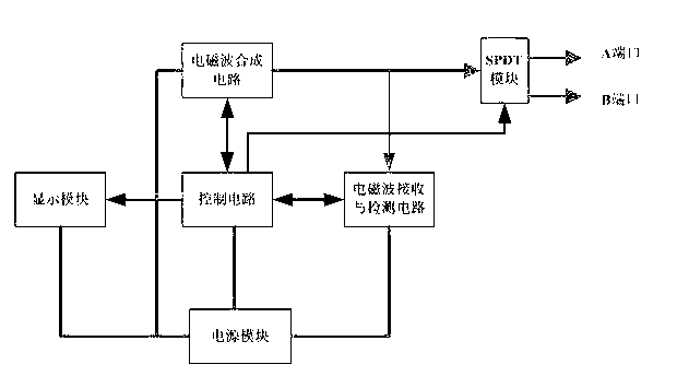
[0018] figure 1 It is a working module diagram of the present invention, and its working method is as follows: the electromagnetic wave synthesis circuit emits electromagnetic waves through the dual-channel radio frequency port 4, and when the electromagnetic waves encounter a fault point, the monitoring equipment records the delay time of the echo return, and equals the electromagnetic wave propagation speed multiplied according to the distance X At that time, the rate factor delay time of the medium, the delay time is replaced by the position where the echo occurs, that is, the position information of the fault point, and then the standing wave ratio is transmitted to the network management unit. If the standing wave ratio is less than or equal to 1.4, the leaky cable is considered to be working normally. ; If the standing wave ratio is greater than 1.4 and less than 1.6, it is considered a general alarm, and there may be a loose connector problem, but this loosening will not...


PUM


Abstract

The invention provides a leaky cable /antenna feeder real-time monitoring apparatus and a working method thereof. The real-time monitoring apparatus is composed of a power supply module, an SPDT module, an electromagnetic wave synthesis circuit, an electromagnetic wave receiving and detection circuit, a display module and a control circuit. An electromagnetic wave is generated by the electromagnetic wave synthesis circuit; an output port is selected by a dual-channel radio frequency port of the SPDT module so as to output an electromagnetic wave signal to an antenna feeder or a leaky cable; when the electromagnetic wave runs into a fault point and is reflected the electromagnetic wave receiving and detection circuit receives the electromagnetic wave, detects the signal intensity and sends data to the control circuit; and the control circuit determines a fault level and fault position according to the detected data and sends the determination information to an alarm display lamp, and the fault position and the fault level are sent to a network management center by a network cable interface so as to display the information for the staff. According to the invention, the following beneficial effects are as follows: a fault point positioning function, a real-time on-line monitoring function, a dual-channel monitoring function and a function of adjustability of frequency for monitoring are realized, thereby providing convenience for fault monitoring of a leaky cable or an antenna feeder.

Description

technical field [0001] The invention relates to the field of leakage cable and antenna feeder monitoring, in particular to a leaky cable / antenna feeder real-time monitoring device and a working method thereof. Background technique [0002] At present, there are two main ways to detect antenna feeder and leaky cable: [0003] One is to inspect the antenna feeder or leaky cable by hand-held detection equipment. This method is time-consuming and has a high workload of manpower. It is no longer suitable for large-scale railway leaky cable / antenna feeder detection. [0004] Another real-time antenna feeder leaky cable device is called master-slave antenna feeder / leakage cable status real-time monitoring system. The characteristics of attenuation, install the host device (radio frequency transceiver module) at a section of antenna feeder / leakage cable, the host device sends a carrier signal of a certain frequency and couples to the antenna feeder / leakage cable for transmi...

Claims


Application Information

Patent Timeline
Patent Type & Authority Applications(China)
IPC IPC(8): G01R31/08
Inventor 倪小龙周霞文吉荣新
Owner NANJING TICOM TECH
Why Eureka
Try Eureka