
Novel power distributor

A power distributor, a new type of technology, applied in the direction of circuits, electrical components, coupling devices, etc., can solve the problems of inconvenient assembly and disassembly maintenance, cumbersome bolt connection, unfavorable shielding insulation, etc., to achieve convenient assembly and disassembly maintenance, save assembly time, seal The effect of better stability and flatness

Active Publication Date: 2013-10-09
FUZHOU XINCHUANG ELECTRIC CO LTD
View PDF4 Cites 2 Cited by
  • Summary
  • Abstract
  • Description
  • Claims
  • Application Information

AI Technical Summary

Problems solved by technology

[0002] The power distributor is usually used for independent power supply of multiple instruments or devices. At present, most of the commonly used power distributors are made of two shells connected by bolts. Shield insulation

Method used


Image

  • Novel power distributor
  • Novel power distributor
  • Novel power distributor

Examples


Embodiment Construction

[0015] In order to make the above-mentioned features and advantages of the present invention more comprehensible, the following specific embodiments are described in detail with reference to the accompanying drawings, but the present invention is not limited thereto.

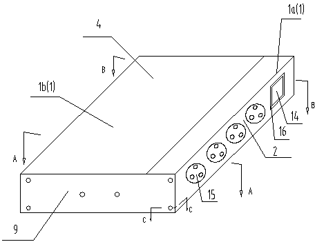
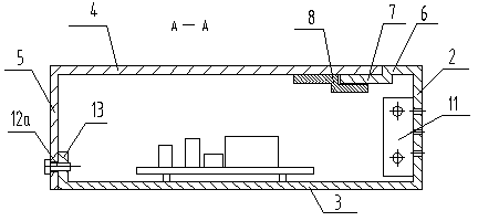
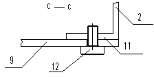
[0016] Referring to Figure 1, figure 2 , image 3 , Figure 4, Figure 5 , Image 6 and Figure 7 , a new type of power distributor, including a box body 1, the box body 1 is used to install the main box body 1a and the rear cover body 1b for installing a power circuit and a row of sockets.

[0017] In this embodiment, the main box body 1a is composed of the front side plate 2 for installing the power socket and the bottom plate 3 for installing the working circuit. The rear cover body 1b is composed of the top plate 4 and the rear end of the top plate The rear side panels 5 are vertically connected to each other.

[0018] In order to facilitate the fit between the main box body and the rear cover, improve ...


PUM


Abstract

The invention relates to a novel power distributor. The novel power distributor comprises a box body. The box body is composed of a main box body used for installing a power circuit and a series of sockets, and a back cover body in a splicing mode. The novel power distributor is simple in structure, forms grounded shield easily, and is convenient to assemble, disassemble and maintain and good in market prospect.

Description

technical field [0001] The invention relates to a novel power distributor. Background technique [0002] The power distributor is usually used for independent power supply of multiple instruments or devices. At present, most of the commonly used power distributors are made of two shells connected by bolts. Shield insulation. Contents of the invention [0003] The purpose of the present invention is to provide a new type of power distributor, which has a simple structure, good sealing performance, convenient assembly and disassembly, and is beneficial to users. [0004] The novel power distributor of the present invention includes a box body, and the box body is composed of a main box body and a rear cover body for installing a power circuit and a row of sockets. [0005] Further, the main box body is composed of a front side plate for installing a power socket and a bottom plate for installing a working circuit, and the rear cover is composed of an inlaid top plate and a...

Claims


Application Information

Patent Timeline
Patent Type & Authority Applications(China)
IPC IPC(8): H01R13/502H01R13/648
Inventor 陈亮
Owner FUZHOU XINCHUANG ELECTRIC CO LTD
Learn More