Data center network topology structure and routing method thereof

A data center network and topology technology, applied in the Internet field, can solve problems such as expensive multi-port network cards, high construction costs, and cost reduction, and achieve the effect of solving link failures, reducing network bandwidth, and improving bandwidth.

Active Publication Date: 2013-10-09
广州云硕科技发展有限公司
View PDF2 Cites 14 Cited by
  • Summary
  • Abstract
  • Description
  • Claims
  • Application Information

AI Technical Summary

Problems solved by technology

[0004] At present, most data center networks are based on a tree structure, which has the following disadvantages: first, high-level switches or routers are likely to become bandwidth bottlenecks; second, core switches or routers are single points of failure in the system; third, high-end communication equipment Using will result in an expensive build
For example, Fares et al. proposed an improved tree structure Fat-Tree, which transforms the traditional tree structure through more cheap switches and connections, improves fault tolerance and network bandwidth, but its scalability is still Limited by the number of switch ports
The DCell proposed by Guo Chuanxiong of Microsoft Asia Research Institute has high scalability, fault tolerance and network bandwidth, but it uses more expensive multi-port network cards (such as four ports) and more complicated connection methods, which will increase Difficulty managing large deployments and resulting in higher build costs
FiConn proposed by Li Dan et al. uses cheap switches and dual-port network card servers, but it uses part of the performance loss in exchange for cost reduction.

Method used


Image

  • Data center network topology structure and routing method thereof
  • Data center network topology structure and routing method thereof
  • Data center network topology structure and routing method thereof

Examples


Embodiment

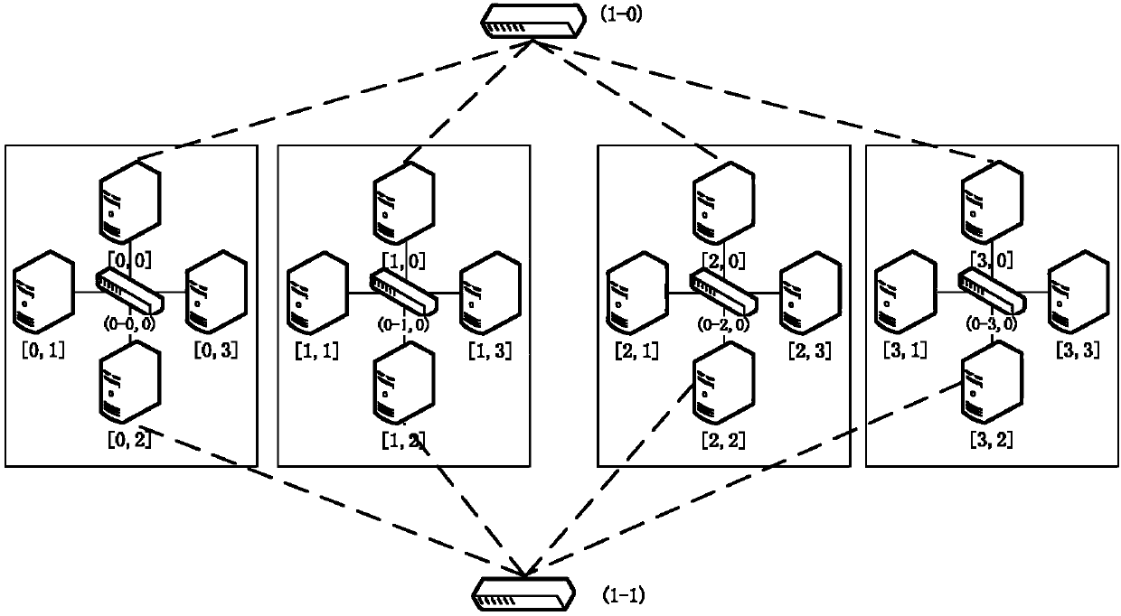
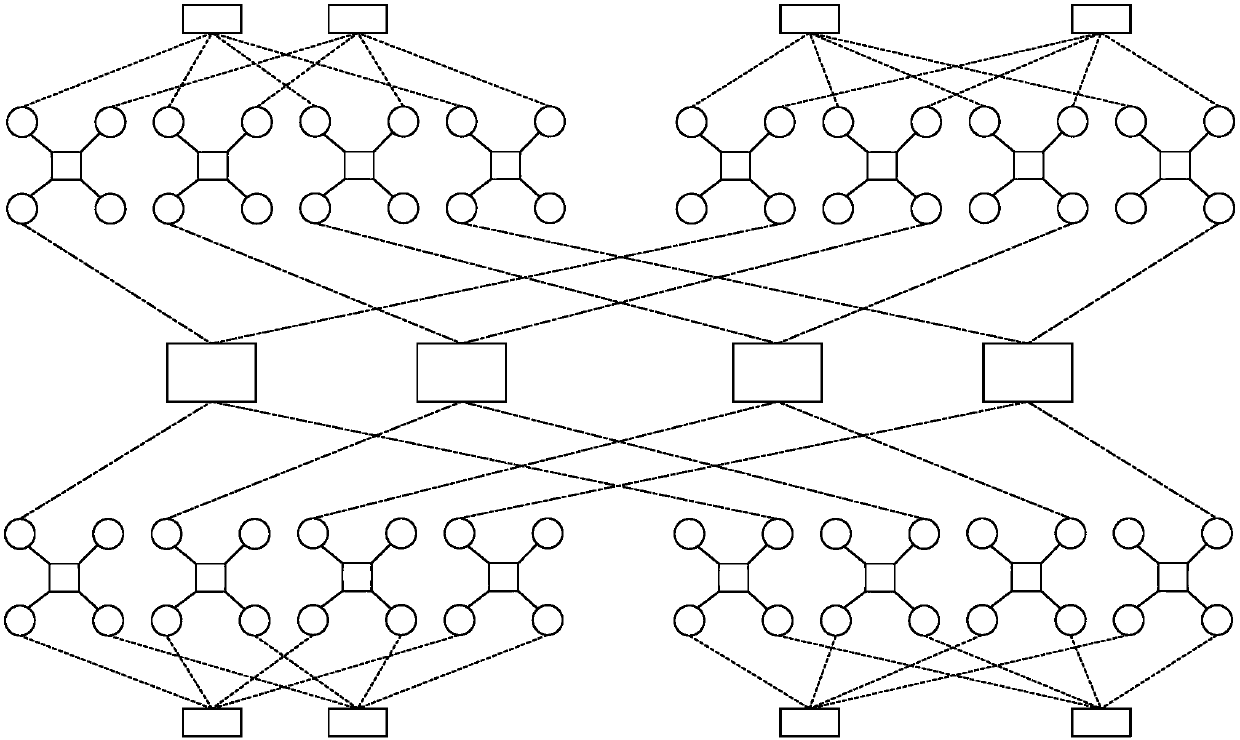
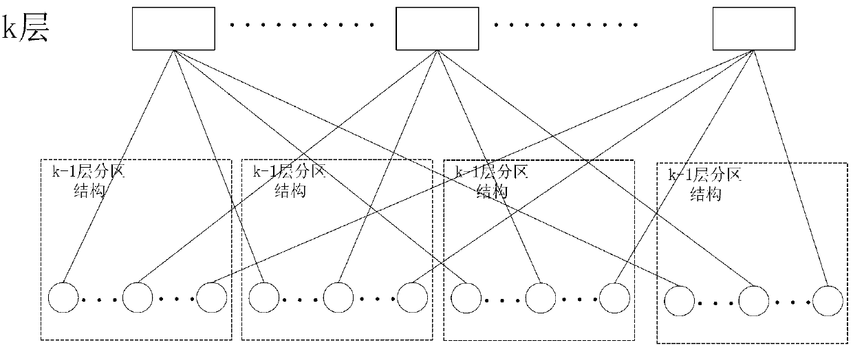
[0039] This embodiment discloses a data center network topology, including a switch and a server, and each server includes two network card ports, such as figure 1As shown, a switch has 4 ports, one of which is connected to 4 servers to form the bottom layer partition structure of the topology, that is, the 0-layer partition structure; at this time, each server only uses one network card port, so each There are 4 unused network card ports in the bottom partition structure, and the 2 unused server network card ports in the 4 bottom partition structures are respectively connected to 2 switches to form a network such as figure 1 In the layer 1 partition structure shown, the 4 server NIC ports connected to each switch come from the 4 bottom layer partition structures respectively. The switches connected to the two unused network card ports in each bottom-level partition structure are different, that is, when constructing a higher-level partition structure, each server network card...


PUM


Abstract

The invention discloses a data center network topology structure and a routing method of the data center network topology structure. The data center network topology structure comprises switches and servers. Each server comprises two network card ports. Each switch is provided with n ports. One switch is connected with n severs to form a partition structure at the bottommost layer of the topology structure. Half number of the server network card ports not used in each of n low-layer partition structures are connected to all the switches respectively to form a high-layer partition structure. The n server network card ports connected to all the switches are from the n low-layer partition structures respectively. In this way, the whole topology structure is formed recursively layer by layer. The data center network topology structure has the advantage of expandability and high fault tolerance.

Description

technical field [0001] The invention belongs to the technical field of the Internet, and in particular relates to a data center network topology structure and a routing method thereof. Background technique [0002] The data center network refers to the network infrastructure of the data center. It connects a large number of servers through high-speed links and switches. The data center network is the core infrastructure of the hardware part of the data center. Its topology structure provides all the switches in the data center. The connection relationship with the server determines the specific organizational form of the data center. [0003] With the development of digitalization of information resources, a large amount of data is generated every day in many fields such as industrial manufacturing, e-commerce, scientific research and teaching, life and entertainment. It is an inevitable trend of the development of today's era that the scale of data is getting larger and fa...

Claims


Application Information

Patent Timeline
Patent Type & Authority Applications(China)
IPC IPC(8): H04L12/751H04L12/721H04L12/707H04L45/02H04L45/24
Inventor 邓玉辉谢俊杰
Owner 广州云硕科技发展有限公司
Why Eureka
Try Eureka