Glove for grasping fine component

A technology for gloves and objects, applied in the field of gloves for grasping small objects, can solve problems such as dead space, inability to float or place small objects, and hindering the grasping of small objects.

Inactive Publication Date: 2013-10-09
株式会社乔恩克罗斯
View PDF7 Cites 0 Cited by
  • Summary
  • Abstract
  • Description
  • Claims
  • Application Information

AI Technical Summary

Problems solved by technology

[0006] First, the ends of the thumb and index finger are usually used to grasp small objects, but due to the thickness of the glove material that makes up the glove, in order to grasp small objects, the place where the thumb and index finger meet becomes short and thick, thus forming a grip. dead space
[0007] Second, when a finger is inserted into the space of the finger part of the glove, there is a redundant space inside the glove relative to the size of the finger. Therefore, when the end part of the finger of the glove touches an object, wrinkles will be formed according to the redundant space, which hinders the grip of small objects
[0008] Third, there are fingernail shapes on people's hands, so when grasping small objects of limited size, that is, when grasping small objects such as semiconductor chips, mechanical pencil leads, larvae, and insect eggs, let the thumb and forefinger The fingernails are partly symmetrical and the grip is achieved by exerting an appropriate grip force while ensuring a stable grip position and a balance between the objects to be gripped, but there is no fingernail shape on the glove
[0009] Fourth, when the shape of the object is a round ball or a round ring rod and it is difficult to ensure or maintain the grip point, use fingernails and other parts to grasp the lower end of the center of the grasped object to make the small object float according to the mechanical principle. Up to the upper part, so that it can be grasped by being placed between the fingernails and fingerprints, but it cannot float or settle small objects after wearing gloves

Method used


Image

  • Glove for grasping fine component
  • Glove for grasping fine component
  • Glove for grasping fine component

Examples


Embodiment Construction

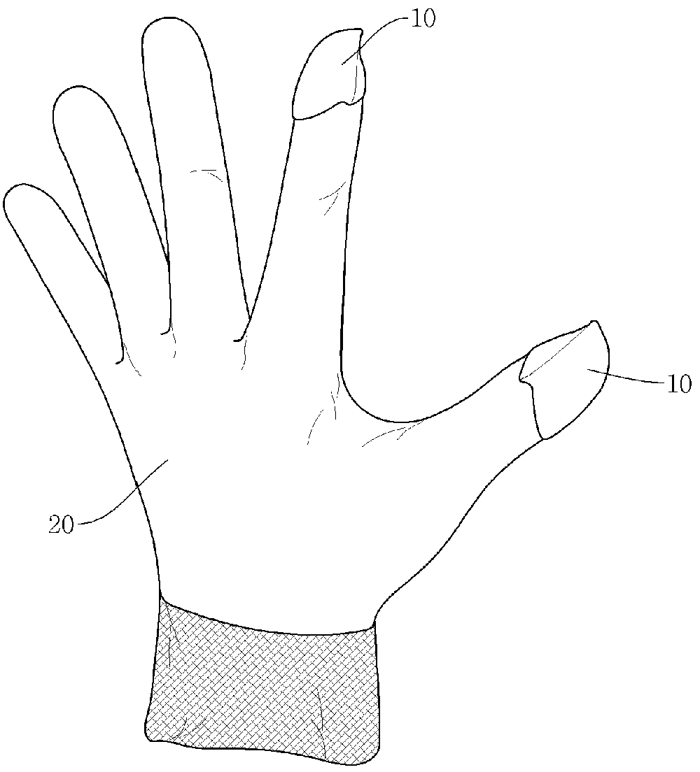
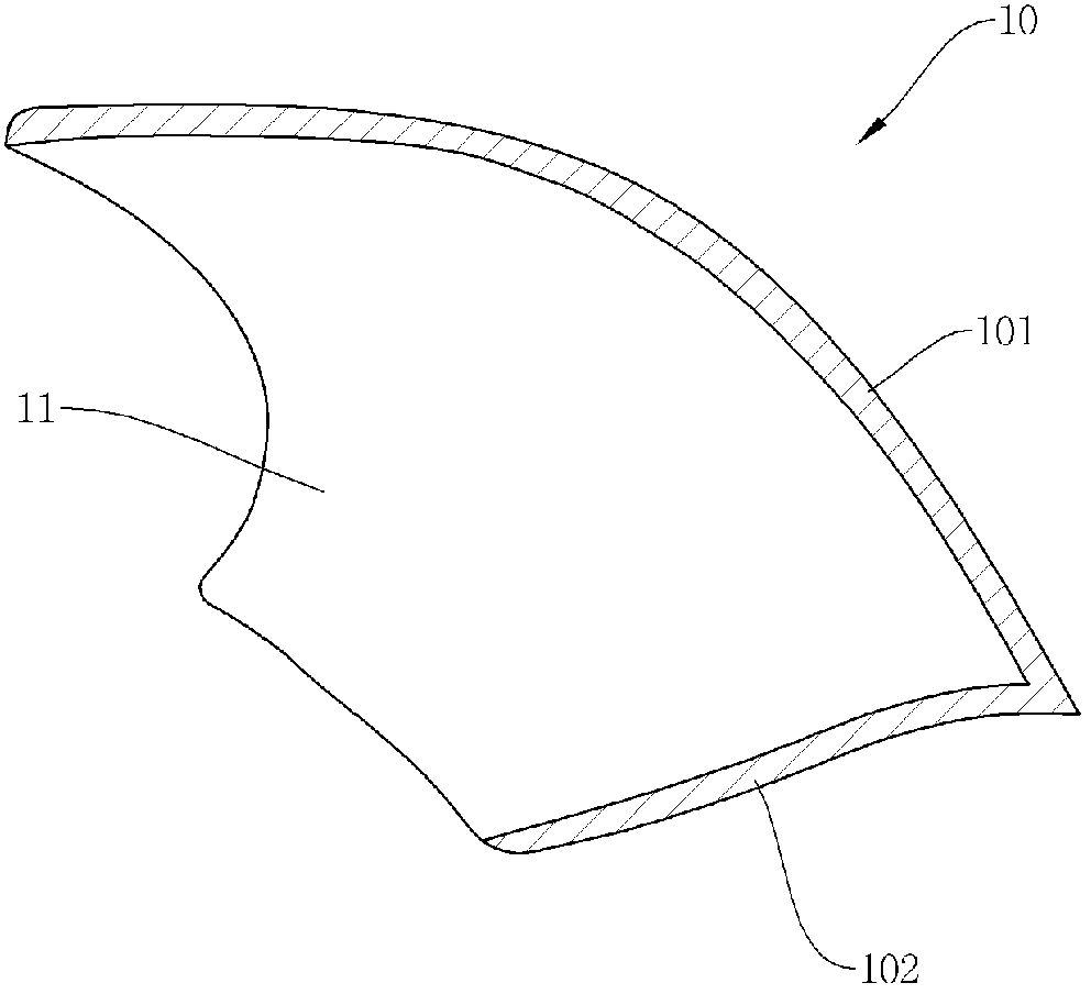
[0043] Embodiments of the present invention will be described in detail below in conjunction with the accompanying drawings. Component elements that can be described using the same name in each figure are assigned the same figure symbol for convenience of description. figure 1 It is a perspective view of a glove for grasping small objects according to the first embodiment of the present invention, figure 2 yes figure 1 A cross-sectional view along line II' is shown.

[0044] see Figure 1 to Figure 2 , The glove for grasping small objects in this embodiment includes: a glove body, including a finger portion 20 wrapping fingers; and a fingertip portion 10 .

[0045] The fingertip portion 10 is formed at the end of the finger portion of the glove, and it includes a first layer 101 facing the back of the hand and a second layer 102 opposite to the first layer 101. The first layer 101 and the second layer 102 are in the The fronts are joined together to form a structure that ...


PUM


Abstract

The present invention relates to a glove for grasping fine components. The glove includes: a glove body including a finger part; and a thimble part in which a first layer, and a second layer opposite the first layer, are bonded together so as to define an edge line, the rear side of the thimble part being open and the thimble part being mounted on the finger part. When a user puts on the glove such that each of the front ends of the thimble part corresponding to the thumb and index finger are aligned with each other, a left / right center line of the outer surface of the first layer of the thimble part of the thumb and a left / right center line of the outer surface of the first layer of the thimble part of the index finger may be aligned with each other with a margin of error of around 0 mm to around 0.5 mm. The angle defined by both left / right center lines in a viewing direction facing the first layer of the thimble part may range from around 170 DEG to around 190 DEG . A common contact plane of the thumb and the index finger may be defined on a point at which both left / right center lines are aligned with each other.

Description

technical field [0001] The present invention relates to a glove for grasping fine components, in particular to a glove for grasping fine components having a structure of a thumb part and a forefinger part which are easy to grasp the fine components. Background technique [0002] The purpose of existing gloves is to protect the user's hands or to protect the user's hands from the external temperature, but recently the function of gloves has surpassed the simple purpose of protecting the hands of the operator, thus there have been cut-resistant gloves, non-slip gloves, heat-resistant Gloves, winter gloves, acid-resistant gloves, salt-resistant gloves, shock-absorbing gloves, oil and dirt handling gloves and all kinds of gloves. [0003] This glove is formed using a material such as cloth of a predetermined thickness in order to protect the hand. However, it is difficult for the user to grasp small tools such as needles, pins, nails, and screws when wearing gloves, so it is ne...

Claims


Application Information

Patent Timeline
Patent Type & Authority Applications(China)
IPC IPC(8): A41D19/015A41D19/00
CPCA41D19/0024
Inventor 李荣太李俊赩
Owner 株式会社乔恩克罗斯
Why Eureka
Try Eureka