Operation lever structure

一种操作杆、连杆的技术,应用在控制构件、直线运动轴、仪器等方向,能够解决辊轴难顺畅运动、危及操作杆操作性能等问题,达到提高操作性能的效果

Inactive Publication Date: 2009-05-27
HONDA MOTOR CO LTD
View PDF0 Cites 0 Cited by
  • Summary
  • Abstract
  • Description
  • Claims
  • Application Information

AI Technical Summary

Problems solved by technology

In the case where foreign matter enters and accumulates in the bottom, it becomes difficult for the roller shaft to move smoothly along the bottom, jeopardizing the operability of the operating lever

Method used


Image

  • Operation lever structure
  • Operation lever structure
  • Operation lever structure

Examples


Embodiment Construction

[0026] The following describes a walking-type power tillage machine as an embodiment of the working machine according to the present invention.

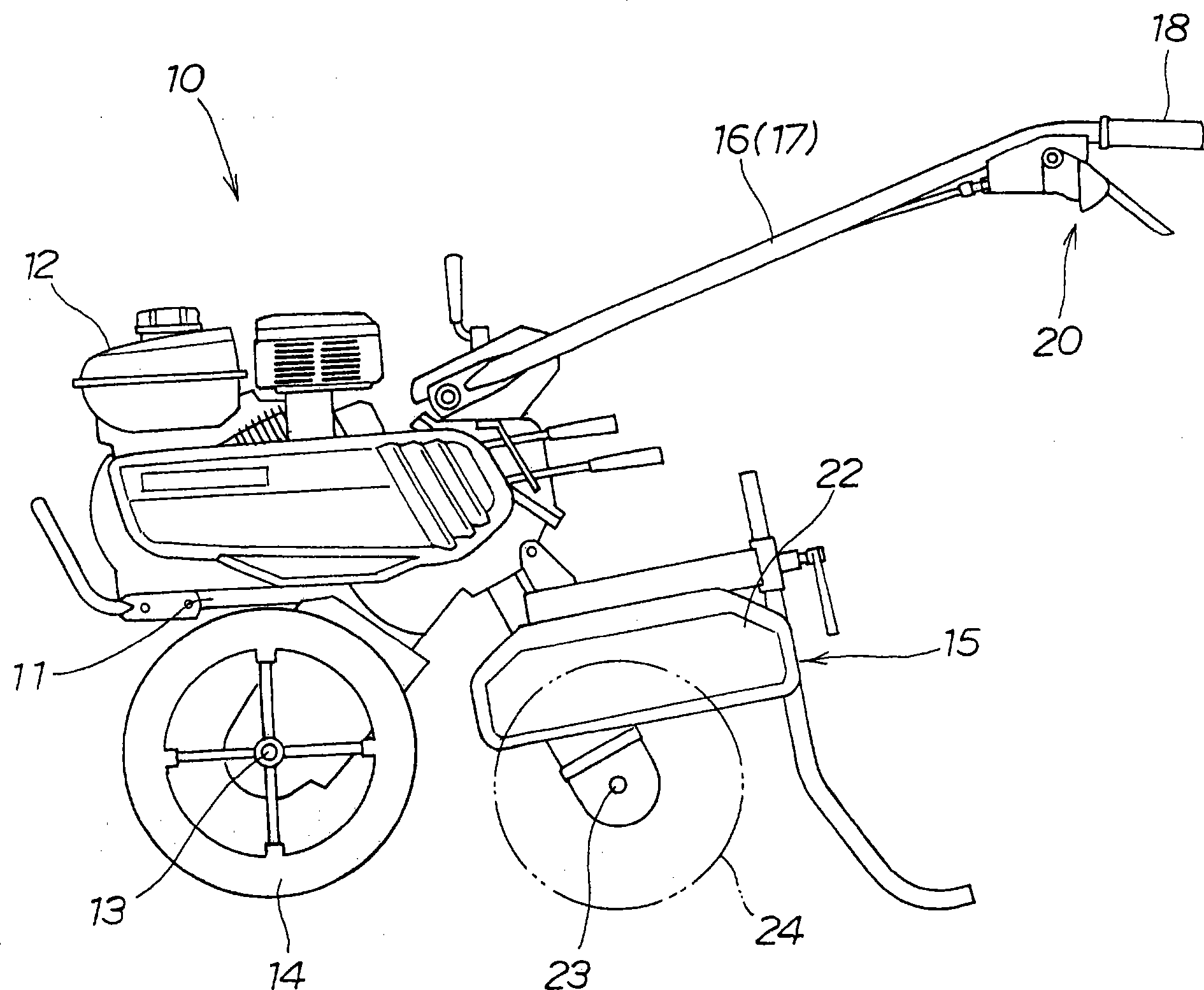
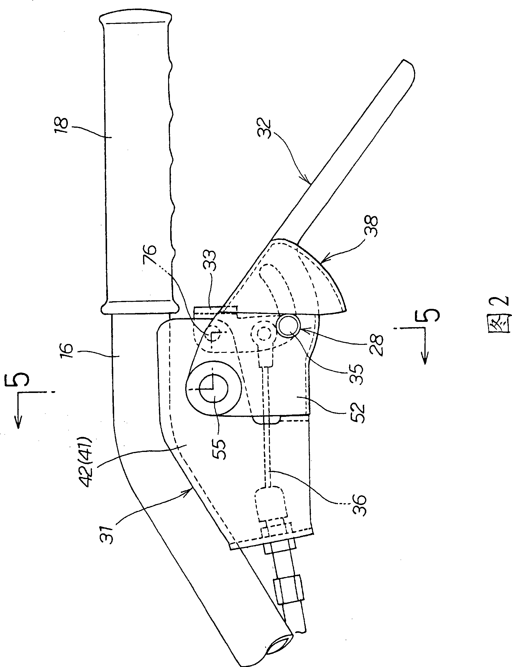
[0027] Such as figure 1 As shown, the walking work machine 10 includes: an engine 12, which is installed on the upper part of the machine body 11; left and right wheels 14, which are arranged on the lower end of the machine body 11 through an axle 13; and a tillage device 15 which is arranged on the machine body. 11; the left and right handles 16, 17, which are arranged at the rear of the machine body 11; and the operating lever structure 20, which is arranged near the left grip 18 of the left handle 16.

[0028] The farming device 15 includes: a farming cover 22 attached to the rear of the machine body 11 so as to be able to move up and down; a farming claw 24 provided on a rotating shaft 23 under the farming cover 22; and a power transmission part (not shown) ), which is used to transmit the rotation of the engine 12 to the rotating s...


PUM


Abstract

An operation lever structure is provided, wherein an operation lever is pulled toward a left handle to cause a link to swing-move to thereby operate an operation cable. The operation lever structure is configured so that each of inside and outside rollers are provided to an opposite end of the link. Inside and outside guide holes for movably supporting the inside and outside rollers are formed in each of a pair of inside and outside side walls. A discharge opening is formed in a bottom part of the operation lever for discharging a foreign matter that has entered the operation lever.

Description

Technical field [0001] The present invention relates to an operating rod structure. In the operating rod structure, by pulling the operating rod toward the handle, the connecting rod is swung and the operating cable is operated. Background technique [0002] Among the operating lever structures of working machines, it is known in the prior art and disclosed in Japanese Utility Model Application Publication No. 64-114 (JP-U64-000 114 A), which It has: an operating rod swayably provided to the handle, a connecting rod arranged between the operating rod and the handle, and an operating cable connected to the connecting rod, one end of the connecting rod is rotatably attached to the handle, and the other One end is movably supported on the operating rod. [0003] The roller shafts are rotatably arranged at the other end of the connecting rod of the operating rod structure, and these roller shafts are movably supported on the bottom of the operating rod. Therefore, when the operating ...

Claims


Application Information

Patent Timeline
Patent Type & Authority Applications(China)
IPC IPC(8): G05G1/04
CPCG05G1/04B62D51/001F16C1/18Y10T74/20438
Inventor 饭野启司宫原一嘉酒井征朱
Owner HONDA MOTOR CO LTD
Why Eureka
Try Eureka