Eureka AIR delivers breakthrough ideas for toughest innovation challenges, trusted by R&D personnel around the world.

Furniture hinge

A furniture and hinge technology, applied in the field of furniture

Active Publication Date: 2015-07-01
JULIUS BLUM GMBH
View PDF8 Cites 0 Cited by
  • Summary
  • Abstract
  • Description
  • Claims
  • Application Information

AI Technical Summary

Problems solved by technology

The disadvantage of this construction is that the curved lugs no longer allow movement between the upper and lower parts

Method used


Image

  • Furniture hinge
  • Furniture hinge
  • Furniture hinge

Examples


Embodiment Construction

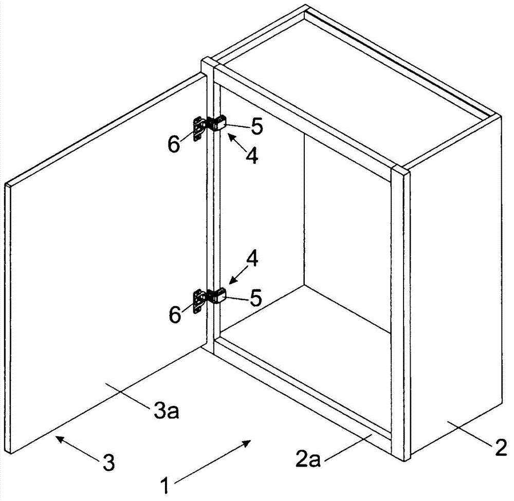
[0030] figure 1 A perspective view of a piece of furniture 1 is shown, in which a movable piece of furniture 3 in the form of a door 3 a is pivotally mounted via two or more furniture hinges 4 relative to a piece of furniture body 2 . The furniture hinge 4 has, in a known manner, a hinge arm 5 to be fastened to a frame 2 a and a hinge cup 6 pivotably connected to the hinge arm 5 . The hinge arms 5 are each fastened to the frame 2 a of the furniture body 2 via a (not visible here) base plate 7 . The hinge cup 6 is embedded in a corresponding hole in the door 3 as known per se.

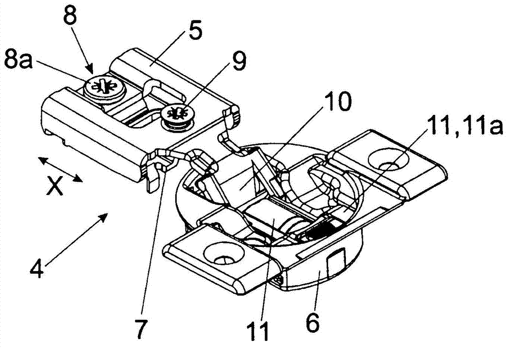
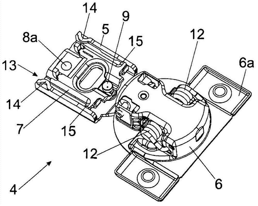
[0031] Figure 2a Shows a perspective view of a furniture hinge 4 with a base plate 7 to be mounted on the furniture body 2 and a hinge arm 5 resting on the base plate 7, the hinge arm 5 is positioned along the drawn line via an adjustment device 8 The direction of the double arrow (X) is movable relative to the substrate 7 . The adjusting device 8 includes a rotatably mounted actuating element 8 a,...


PUM


Abstract

The invention relates to a furniture hinge comprising a base plate, which is designed to be fastened to a furniture body, and a hinge arm that is mounted so as to be movable by an adjustment device in a controlled manner relative to the base plate within a predetermined adjustment range, wherein the adjustment device prevents the hinge arm from falling from the base plate by displacement. The furniture hinge has a fall guard for the hinge arm which prevents the hinge arm from falling relative to the base plate upon uncontrolled displacement of the hinge arm caused by failure of the adjustment device, and the hinge arm is mounted so as to be movable relative to the base plate within the predetermined adjustment range despite the fall guard.

Description

technical field [0001] The invention relates to a furniture hinge. [0002] Furthermore, the invention relates to a piece of furniture with at least one furniture hinge of the type to be specified. Background technique [0003] Such an adjusting device can adjust the door hingedly connected with the furniture in the depth direction, so that the distance of the door relative to the front side of the furniture body can thus be adjusted. The adjustment device for depth adjustment can comprise a rotatably mounted actuating element, for example in the form of an eccentric screw, which is connected to the base plate and which, when actuated by a user, moves the hinge arm relative to the base plate. [0004] A furniture hinge with such an adjusting device is described, for example, in DE 203 19 539 U1 by the applicant. According to one exemplary embodiment, the depth adjustment device can have an eccentric screw that is riveted to the base plate. However, the industrial producti...

Claims


Application Information

Patent Timeline
Patent Type & Authority Patents(China)
IPC IPC(8): E05D7/04E05D11/00
CPCE05D7/0009Y10T16/53235E05Y2201/224E05Y2900/20Y10T16/53225Y10T16/5321E05D11/00Y10T16/554Y10T16/53253E05D7/0407E05D7/0423E05D7/0415Y10T16/532Y10T16/551
Inventor D·哈格斯皮尔
Owner JULIUS BLUM GMBH
Why Eureka
Eureka Blog
Learn More