Jigsaw automatic welding machine and unit

An automatic welding machine and piecing technology, applied in welding equipment, auxiliary welding equipment, welding/cutting auxiliary equipment, etc., can solve the problems of high labor intensity, low production efficiency, hidden dangers of workers, etc., to eliminate hidden dangers and improve safety. The effect of production efficiency and labor intensity reduction

Active Publication Date: 2016-03-02
CHINA INTERNATIONAL MARINE CONTAINERS (GROUP) CO LTD +1
View PDF6 Cites 0 Cited by
  • Summary
  • Abstract
  • Description
  • Claims
  • Application Information

AI Technical Summary

Problems solved by technology

However, the bearing row does not have power, and it often needs to be manually pushed during transmission. The labor intensity of the workers is high, there are certain safety hazards, and the production efficiency is low. Moreover, the transmission is particularly difficult for special plates with reinforcing beams or ribs on the back.

Method used


Image

  • Jigsaw automatic welding machine and unit
  • Jigsaw automatic welding machine and unit
  • Jigsaw automatic welding machine and unit

Examples


Embodiment Construction

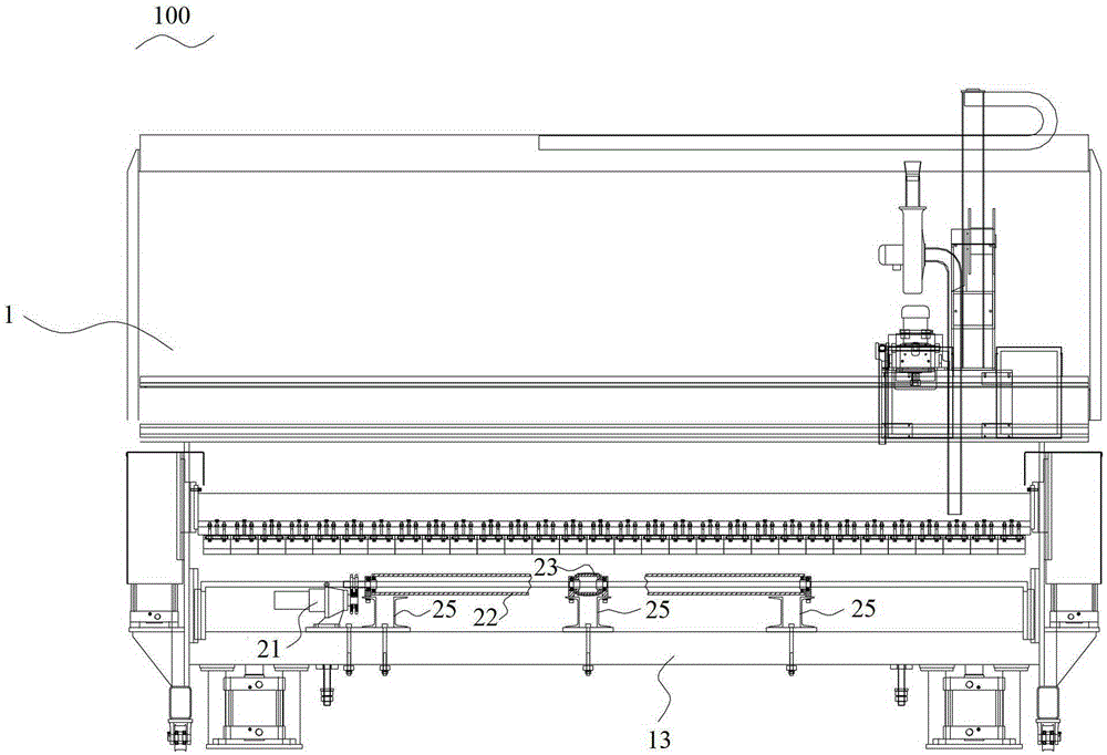
[0018] In order to further illustrate the principle and structure of the present invention, preferred embodiments of the present invention will now be described in detail with reference to the accompanying drawings.

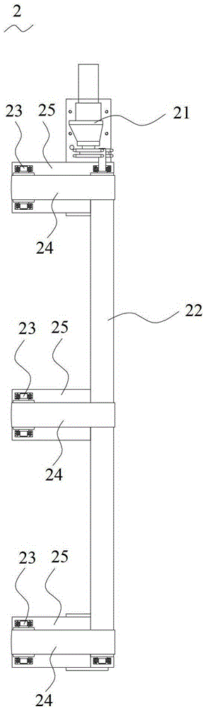
[0019] refer to figure 1 , the plate power transmission mechanism 2 of the present invention is applied to an automatic panel welding machine, and the plate power transmission mechanism 2 includes: a motor reducer 21 , a driving wheel 22 and three driven wheels 23 .

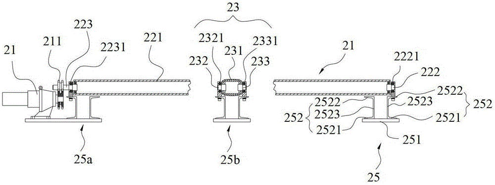
[0020] combined reference figure 2 The driving wheel 22 comprises: a cylindrical driving roller 221 and two driving shafts 222, 223 respectively fixed at both ends of the driving roller, and each driving shaft 222, 223 is connected to the axial center of the driving roller 221. Each driven wheel 23 is located at one side of the length direction of the driving wheel 22 and is distributed at intervals along the length direction of the driving wheel 22, wherein two driven wheels 23 are close to the t...


PUM


Abstract

The invention discloses a jointed board automatic welder, a joint board automatic welder unit and a board power transmission mechanism. The joint board automatic welder unit comprises a plurality of jointed board automatic welders. The jointed board automatic welder comprises a machine table, a welding copper bar and two board power transmission mechanisms, wherein the welding copper bar is arranged on the machine table. The board power transmission mechanism comprises a motor reducer, a driving wheel and at least two driven wheels. All the driven wheels are respectively located at one side of the length direction of the driving wheel and are spaced along the length direction of the driving wheel; each driven wheel is connected with the driving wheel by a belt; and the motor reducer is connected with one end of the driving wheel so as to drive the driving wheel to rotate, and further, the belt connected with the driving wheel and the driven wheels are driven to rotate, so that a board located on each belt is transmitted along the belt. According to the board power transmission mechanism, not only can the automatic transmission of the board be realized but also the spacing adjustment of the unit cannot be influenced, and when the number of the machine tables is changed, the machine tables can be rapidly combined to meet the production requirements of special containers.

Description

technical field [0001] The invention relates to an automatic panel welding machine, in particular to a plate power transmission mechanism applied to the automatic panel welding machine. Background technique [0002] The side panels, roof panels and steel floors of the container need to be welded and welded by the automatic panel welding machine. Since the container plates have multiple welds, usually multiple welding machines are combined into one unit to complete the welding of the container plates at one time, thereby improving the welding efficiency. The spacing between standard container plates generally does not change, so the welding seam spacing between the machines does not need to be adjusted, and a fixed power transmission mechanism can be installed between the machines. However, the structure of the special container is complex, and the distance between the welds between the plates is often changed. The maximum distance is 1500mm, and the minimum distance is 800m...

Claims


Application Information

Patent Timeline
Patent Type & Authority Patents(China)
IPC IPC(8): B23K37/00
Inventor 陆健辉王飞邵飞刘佰纯
Owner CHINA INTERNATIONAL MARINE CONTAINERS (GROUP) CO LTD
Why Eureka
Try Eureka